Download
1 / 28
280 likes | 325 Views
Discover different types of lines and symbols used in construction drawings, various views like plan and perspective, along with key elements such as topography and plot plans. Learn how to interpret symbols, read contour maps, and understand cross-sections and profiles on blueprint drawings.

E N D
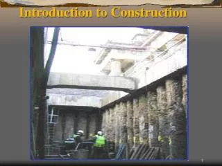
CE 303: Introduction to Construction Blueprint Lab
Construction Drawings Blueprints Lines, Symbols, and Views
Objectives • Types of lines and symbols • Various types of views used in drawings • Topography/contour maps • Profiles • Cross Sections • Plot Plans
Legends • List of symbols used to identify features in the drawing. • Every symbol and line type used in the drawing will have a corresponding entry in the legend.
General Line Types(Alphabet of Lines) • Property Lines • Border Lines • Object Lines • Hidden Lines • Center Lines • Dimension and Extension Lines • Break Lines • Cutting Plane Lines or Section Lines
Alphabet of Lines property line border line object line hidden line center line
Alphabet of Lines Dimension Line dimension & extension lines 23’-6” Extension Line
Alphabet of Lines break lines long short
Alphabet of Lines section identification sheet number location of section G S12 cutting-plane lines direction section is facing F A5 B B
Blueprint View Types • Plan Views • Orthographic/Perspective • Detail Views • Contour/Topographic Views • Cross-sections • Profiles • Plot Plans
Orthographic Views/Drawings • all construction drawings use orthographic drawings • projected at right angles • more detail can be shown • start with the front view • drawn to true size or scale
Perspective View/Drawings • most realistic • receding lines meet at vanishing points • one - point • two - point
Perspective Drawings Figure 6 - 15 Figure 6 - 11 two - point one - point Figure 6 - 12 Figure 6 - 16
Detail Views • Certain features can not always be clearly shown on construction drawings. • Require a large scale illustration to show all of the details. • May be placed on the same sheets as the plan or elevation views or on separate sheets.
Topography & Contours • Contour Lines identify the ground elevation. • All points along a single contour line have the same elevation. • The interval between contours can represent any convenient distance. (i.e. 1’, 2’, 5’, etc…) • Topography is the location and elevation of features, consisting of both natural and man-made objects.
Cross Sections • Cross sections show the “inside” of a structure, or the elevations of the earth and structures along a station. • Used heavily in earthworks and highway construction. • Provided for features whose construction is not shown clearly on plan or elevation drawings.
Profiles • Profiles are vertical sections through a topographic map that shows the earth’s surface at any location along an alignment. • Profiles often have a vertical exaggeration in order to show more detail of the surface.
Plot Plans(Site Plans) • View from above the property that illustrates location of building on the lot. • Lot and block number or address • Bearing and length of property lines • North arrow • Dimensions of front, rear and side yards. • Location of other accessory buildings • Location of walks, drives, fences, etc… • Location of Utilities, and easement setbacks • Elevations at various locations • Etc…