Download
1 / 64
730 likes | 1.07k Views
Encoders Three-state Outputs Multiplexers XOR gates . Encoders. An encoder is a combinational logic module or a digital circuit that performs the inverse operation of a decoder . It assigns a unique output code for each input signal applied to the device.

E N D
Encoders • An encoder is a combinational logic module or a digital circuit that performs the inverse operation of a decoder. • It assigns a unique output code for each input signal applied to the device. • An encoder has 2n (or fewer) input lines and n output lines. • The output lines generate the binary code corresponding to the input value. • An example of an encoder is the octal to-binary encoder, 74148.
Encoders vs. Decoders Decoder Encoder
Decoders • A decoder is multiple-input, multiple-output logic circuit that converts coded inputs into coded outputs. • Input code with fewer bits than the output bits. • Typically n inputs, 2n outputs • 2-to-4, 3-to-8, 4-to-16, etc. • There is a one-to-one mapping.
Decoders • General decoder structure • Typically n inputs, 2n outputs • 2-to-4, 3-to-8, 4-to-16, etc.
Binary 2-to-4 decoder Note “x” (don’t care) notation.
Types of encoders • Encoders with mutually exclusive inputs: • The inputs are mutually exclusive; that is, one and only one of the input lines is active at any particular instant of time. • In this case the input combinations that never occur may be used as don’t-care conditions. • Priority encoders: • It allows multiple input lines to be active and sends out the binary value of the input line with highest priority. • Normally the highest priority is assigned to the highest subscript.
Design an encoder with mutually exclusive inputs: • Design an encoder for four input lines if one and only one is active at any moment in time. • Truth table: • the output function yield the binary value of the input variable’s subscript.
Design an encoder with mutually exclusive inputs: • Karnaugh Map: A0 = X1 + X3
Design an encoder with mutually exclusive inputs: • Karnaugh Map: A1 = X2 + X3
Design an encoder with mutually exclusive inputs: A0 = X1 + X3 A1 = X2 + X3
Need priority in most applications • Inputs indicates a request for service. e.g., Interrupt requests • if multiple requests are made simultaneously, the encoder gives undesirable results. • The solution is to assign priority to the input lines, priority encoder.
Logic symbol for an 8-input priority encoder • Input I7 has the highest priority. • Outputs A2-A0 contain the number of the highest-priority asserted input. • The IDLE output is asserted if no inputs are asserted.
Priority-encoder logic equations • In order to write logic equations for the priority encoder’s outputs, we first define eight intermediate variables H0-H7, such that Hi is 1 if and only if Ii is the highest priority input:
Ambiguity • If two inputs are active simultaneously, the output produces an undefined combination. For example, if X1 andX2 are 1 simultaneously, the output will be 11. This does not represent 1 or 2. To resolve this ambiguity, encoder circuits must establish a priority to ensure that only one input is encoded. • Another ambiguity is that an output with all 0’s is generated when all the inputs are 0. The problem is that an output with all 0’s is also generated when X0 is equal to 1. This ambiguity can be resolved by providing an additional output that specifies the condition that none of the inputs are active.
Design a priority encoder: • Design an encoder for four input lines if one and only one is active at any moment in time. • Truth table: • the output function yield the binary value of the input variable’s subscript.
Design a priority encoder: • Karnaugh Map: A0 = X3 +X1 X’2
Design a priority encoder: • Karnaugh Map: A1 = X2 + X3
Design a priority encoder: • Group Select GS = X0 + X1 + X2 + X3
74x148 8-input priority encoder • Active-low I/O • Enable Input • “Got Something” • Enable Output
Cascading priority encoders • 32-inputpriority encoder
15-input priority encoder in ABEL • Declarations
Alternative formulation • WHEN is very natural for priority function
Three-state buffers • Output = LOW, HIGH, or Hi-Z. • Can tie multiple outputs together, if at most one at a time is driven.
Three-state buffers • When the enable input is not asserted, the device output “floats”; that is, it goes to a high-impedance (Hi-Z), disconnected state and functionally behaves as if it weren’t even there.
timing • Typically three-state devices are designed so that they go into the Hi-Z state faster than they come out of the Hi-Z state. • That ensures the first device to get off the party line before the second one gets on. • Otherwise excessive current will flow. • The safe way to use three-state devices is to design control logic that guarantees a dead time, during which no one is driving the party line.
Standard MSI three-state buffer 74 541 • It has 8 non-inverting three-state buffers. • The little rectangular symbols inside the buffer symbols indicate hysteresis, an electrical characteristics of the inputs that improves noise immunity. • The 74x541 inputs typically have 0.4 volts of hysteresis.
Bus transceiver 74 245 • A bus transceiver contains pairs of three-state buffers connected in opposite directions between each pair of pins, so that data can be transferred in either direction. • A bus transceiver is typically used between two bidirectional buses.
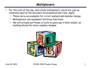
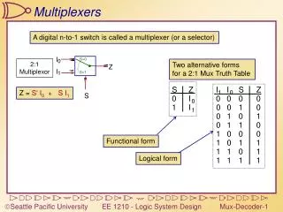
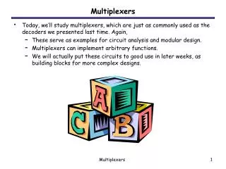
Multiplexers • A multiplexer is a digital switch - it connects data from one of n sources to its output. • An n-input and b-bit multiplexer has n soureces of data, each of which b bits wide, and there are b output bits.a multiplexer is a unidirectional device. • Multiplexers are used in any application in which data must be switched from multiple sourcesto a destination. e.g., processor’s registers to ALU
Multiplexers • A multiplexer is a digital switch - it connects data from one of n sources to its output. • An n-input and b-bit multiplexer has n soureces of data, each of which b bits wide, and there are b output bits.a multiplexer is a unidirectional device. • Multiplexers are used in any application in which data must be switched from multiple sourcesto a destination. e.g., processor’s registers to ALU
Multiplexers n-1 EN . Mj .iDj iY = j = 0 • iY is a particular output bit, • Mj represents minterm j of the s select inputs; and • iDj is the input bit i of source j; • When the mutiplexer is enabled and the value on the select inputs is j, each output iY equals the corresponding bit of the selected input, iDj.
4-input, 1-bit Multiplexer 3 EN . Mj .iDj Y = j = 0 • Y is the output bit, • Mj represents minterm j (0~3) of the 2 select inputs; and • Dj is the input bit of source j; • When the mutiplexer is enabled and the value on the select inputs is j, the output Y equals the corresponding bit of the selected input, Dj.
CMOS transmission gates • 2-input multiplexer
Other multiplexer varieties • 2-input, 4-bit-wide • 74x157 • 4-input, 2-bit-wide • 74x153