Download
1 / 48
500 likes | 725 Views
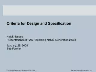
Utility Design Criteria for. Highway Relocation Projects. Florida Utilities Coordinating Committee. Educational Workshop Nov. 5th, 2003. Overhead Electric Distribution Facilities. Design Criteria. What are the requirements of the utility to design a relocation project ?

E N D
Utility Design Criteria for Highway Relocation Projects Florida Utilities Coordinating Committee Educational Workshop Nov. 5th, 2003
Overhead Electric Distribution Facilities
Design Criteria • What are the requirements of the utility to design a relocation project ? • What are some of the problems associated with utility design ? • What are the steps in designing a utility relocation ? • What factors effect the utility relocation design time ? • What is required for the final design to be completed ?
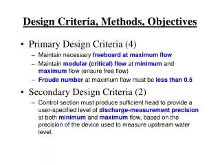
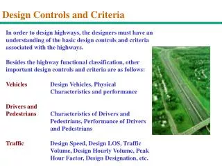
What are the requirements of the utility to design a relocation project? • Limits of any right-of-way acquisitions • Proposed roadway geometry • Existing as well as future site conditions • All major elements of the construction • Bridges or overpasses • Drainage structures • MSE or Noise walls • Signal poles • Roadway lighting poles • Overhead signs
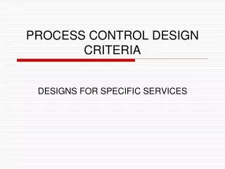
What are some of the problems associated with utility design ? • Design a relocation that meets all the standard construction practices of that utility • Design a relocation that minimizes the impact to the right-of-way (uses as little r/w as possible) • Design a facility that can be maintained during the roadway construction activities • Design for obstructions adjacent to the right-of-way • Design a facility that meets all NESC clearance and safety requirements • Design so that the utility and the roadway can be constructed within the OSHA code requirements
What are the steps in designing a utility relocation ? • Determine future load growth requirements • Access possible alternate routes or realignment within the existing right-of-way • Determine requirements of existing or proposed joint pole users • Determine all permitting requirements associated with the possible design alternatives • Evaluate the the cost to benefit ratios of the possible design alternatives • Evaluate future maintenance requirements of the possible design alternatives
What factors effect the utility relocation design time ? • The complexity of the roadway improvement project • The number and size of the utilities sharing the right-of-way • The permitting requirements of the utility relocation design • Changes in roadway design after the utility design process has begun • Addition or change in drainage, lighting, signalization or signing plans
What is required for the final design to be completed ? • Final roadway plans including all structure and drainage plan sheets • Final signalization, signing and lighting plans • All right-of-way acquisition that effects the utility relocation completed • Final approval for the utility construction from all required permitting agencies • Proposed alignments of all other utilities within the right-of-way • Final MOT and construction phasing plans • Final requirements of all joint pole users
Proposed cantilever sign structure Existing 12,470 volt overhead primary
Closest energized conductor of overhead line OSHA required clearance for sign construction and maintenance = 10’ 0 - 50,000 volts NESC minimum clearance = 6’ 0 - 750 volts 8’ 750 - 22,000 volts Proposed Cantilever sign
Existing overhead 12,470 volt lines To be removed To remain Proposed Existing traffic signal span wires attached to power poles
Proposed Mast arm traffic signals
Existing & proposed 12,470 volt lines & signal span wires with proposed mast arm traffic signals Design Change: Increase pole height on proposed line to provide NESC and OSHA clearances Old poles to remain until removal of signal span wires Result: Maximum clear working height for drill shaft and signal pole installation = 30’ Or contractor and his equipment certified for work on high voltage
Existing & proposed 12,470 volt lines & signal span wires with proposed mast arm traffic signal poles & proposed highway lighting poles No change in proposed design required Contractor and equipment must maintain 10’ clearance from 12,470 volt lines during light pole installation or be certified for high voltage work
Existing 12,470 volt overhead double circuit primary line located at R/W line to remain in place Two existing 230kv transmission steel tower lines to remain in place Proposed bridge structure over Cross Bayou Canal
Vertical clearances also required from 230kv transmission lines 12,470 volt line 12,470 volt line 10’ 10’ Clearance required from 12,470 volt line for bridge structure construction equipment 25’ 20’ Distance from face of pole to face of structure
Existing Transmission Crossing R/W at Cross Bayou Canal, Looking NW
Temporary Overhead Lines to Clear Bridge Construction Phase I MOT
10’ + Proper clearance from existing E/W 12,470 volt line to allow construction of signal pole
Proper vertical clearance from 120 N/S 120 volt line for signal pole maintenance 2’ 5’ Improper horizontal clearance from N/S 12, 470 volt line for signal pole installation
Existing billboard adjacent to R/W Relocated 12,470 volt primary line
Bonded & grounded conductors Underground dip to provide NESC & OSHA clearances
Improper clearance for sign maintenance Sign meats all horizontal requirements as it is but can not be maintained on the N/W face of the sign due to 12,470 volt lines
12,470 volt line 6’ Does this meet code ?
Yes 12’
Relocated pole line R/W Trees at or near the right-of-way line