Download
1 / 37
410 likes | 899 Views
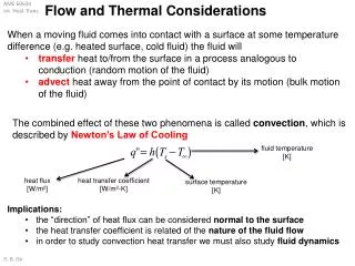
Thermal Management Considerations for PCBs. Measurement techniques and heat conduction Dr Graham Berry. Apple Apps for Thermal Engineers.

E N D
Thermal Management Considerations for PCBs Measurement techniques and heat conduction Dr Graham Berry
Apple Apps for Thermal Engineers Gear3-Finishes is an encyclopedia in your pocket for Thermo-Physical surface properties of hundreds of materials. If you need properties for Asphalt Shingles, Second Surface Silvered Teflon. or even a Deciduous Forest, you can find it here! Gear1-Convection is comprised of three natural convection and three forced convection calculators. It is a visual application designed for touch-based interaction. This provides an instant sensitivity analysis to determine which parameters are the most important. Gear2-Materials is an encyclopedia in your pocket for Thermo-Physical properties of over 1,300 materials. These properties include: Density, Specific Heat, and Thermal Conductivity.
Thermal Resistance • TSP Method (temperature sensitive parameter) • Meets military specifications • Use forward voltage drop of calibrated diode to measure change in Tj due to known power dissipation
Thermal resistance calculation • Recall formula for junction temperature:TJ = (PD x qJA) + TA • Rearranging equation, thermal resistance calculated by: qJA=DTJ/PD=TJ-TA/PD where TJ is junction temp, TA is ambient temp and PD is power dissipation
TSP Calibration • TSP diode calibrated in constant temperature oil bath, measured to ±0.1°C • Calibration current low to minimise self-heating • Normally performed at 25°C and 75°C
Temperature coefficient • Temperature coefficient known as K-factor • Calculated using K=T2-T1/VF2-VF1at constant IF where:K=Temperature coefficient (°C/mV)T1,2 = lower and higher test temperatures (°C)VF1,F2=Forward voltage at IF and T1,2IF=Constant forward voltage measurement current
Calibration graph • K-factor measured from inverse of slope
Thermal resistance measurement • Constant voltage and constant current pulses applied to test device • Constant current pulse is same value as used to calibrate TSP diode • This is used to measure forward voltage • Constant voltage pulse used to heat test device
Thermal resistance measurements • Constant voltage (heating) pulse much longer than constant current (measurement) pulse to minimise cooling during measurement • Typically >99:1ratio
Thermal resistance measurements • Measurement cycle starts at ambient temperature • Continues until steady state reached, i.e. thermal equilibrium
Thermal resistance measurements • Thermal resistance calculated by:qJA=DTJ/PD=K(VFA-VFS)/VH´ IH where: VFA=forward voltage of TSP at ambient temp (mV)VFS=Forward voltage of TSP at equilibrium (mV)VH=Heating voltage (V)IH=Heating current (A)
Test ambient • Measurement of qJA • Devices soldered to special thermal resistance test boards • 8-9 mil (200-225µm) standoff from board • Placed in box of known volume (1cu ft if you’re American!) • Temperature rise measured
Air flow tests • Ambient test can also use moving air • Air flow passed over device at known constant rate • Required for calculations involving active cooling (Lecture 2) • Similar setup to static ambient test
Test setups Test device on board Air flow test setups
qJC Tests • Test device held against an infinite heatsink • This comprises a massive, water-cooled copper block, kept at 20°C • In this way, qCA (case-ambient) is very close to zero, so any measurement is purely qJC (junction-case)
qJC Tests • SO devices mounted with bottom of package against heatsink, using thermal grease for good conductivity • PLCC devices mounted upside down, with top of package against heatsink • Spacer used on bottom side to prevent heat loss from here
qJC data • Power dissipation has an effect on thermal resistance • Must be consideredwhen calculatingcooling requirements
Other factors affecting qJC • Recall from Lecture 1: • Leadframe design, pad size • Larger pads reduce thermal resistance for given die size • Leadframe material - Alloy 42 or copper
qJA data • Air flow also affects qJA • Importantconsiderationfor forced-aircooling
Heatsinks • Purpose of a heatsink is to conduct heat away from a device • Made of high thermal conductivity material (usually Al, Cu) • Increased surface area (fins etc) helps to remove heat to ambient • Interface between heatsink and device important for good thermal transfer
Interface roughness • Surface roughness at interface between two materials makes a huge difference to thermal conductivity • Various different contact configurations on microscopic scale
Surface roughness • Air gaps act as effective insulators • Need some interstitial filler • Many types available, including greases, elastomers, adhesive tapes • Seen by consumers e.g. in PC processor heatsink/fan kits
Solid interfaces • Conforming rough surfaces can have high conductivity:
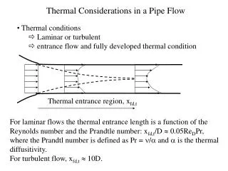
Heat Conduction in a PCB • PCB is layered composite of copper foil and glass-reinforced polymer (FR4)
Heat conduction in PCB • Can treat this layered structure as homogeneous material with two different thermal conductivities • Heat flow within plane is kIn-plane • Heat flow through thickness of plane is kThrough
Conductivity Equations where t is thickness of given layer andk is thermal conductivity of that layer
Sample results • Total PCB thickness is 1.59mm • PCB comprises only copper and FR4 layers • k of copper is 390 W/mK • k of FR4 is 0.25 W/mK
Conclusions from results • Even for thin copper layers, kIn-plane is much greater than kThrough • As FR4 has very low thermal conductivity, a continuous copper layer will dominate heat flow • Because of this, thermal conduction is not efficient where no continuous copper path exists
Refining calculations • Trace (signal-carrying) copper layers have much less effect on heat transfer than planes • Trace layers can normally be excluded from calculations • If required, conductivity of trace layer can be calculated fromwhere fi is fractional copper coverage
Summary • TSP Method for measuring junction temperatures • Thermal resistance test methods - junction-air and junction-case • Effects of power dissipation and airflow on thermal resistance • Interface resistance • Use of interstitial materials to decrease this
Summary • Heat conduction in copper-clad PCB dominated by in-plane transfer • Trace layers have only a small contribution to total conduction • FR4 is a good insulator!
Thermal Analysis Software • PCAnalyze ™ is an engineering application used to mathematically model and predict the thermal behavior of printed circuit assembly (PCA) designs. Component placement, cooling strategies, or "worst case" conditions can be quickly evaluated using this software. • PCAnalyze will calculate the temperature of the board and its individual components, using its integrated steady state and transient solver. This is the same solver used in the TAK2000 Pro™ thermal analyzer. • PCAnalyze ™ is a stand-alone application with its own built-in solver. No third-party compiler, linker, or graphics package is required. http://www.pcanalyze.com/product.htm