Download
1 / 18
480 likes | 1.43k Views
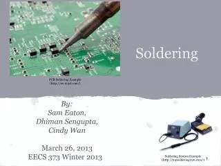
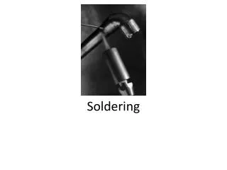
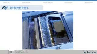
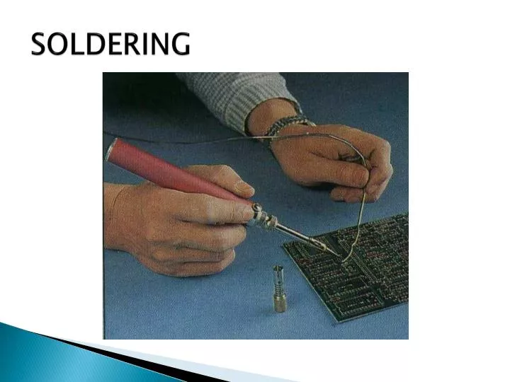
SOLDERING. SOLDERING. SOLDERING Soldering is the process of joining two wires together by the use of a solder alloy Non-solder connections Bolts Rivets Staples Disadvantages Loose connections due to vibration or shock Oxidation Advantages of solder connections

E N D
SOLDERING • SOLDERING • Soldering is the process of joining two wires together by the use of a solder alloy • Non-solder connections • Bolts • Rivets • Staples • Disadvantages • Loose connections due to vibration or shock • Oxidation • Advantages of solder connections • No loose connections when subjected to movement and vibration • No oxidation (No contact surface exposed to oxidize) • Continuous connective path
SOLDERING • Wetting action: It is when (by a chemical reaction, like a solvent) molecules of solder and copper blend together to form a new alloy • SOLDER (A METAL ALLOY) • Solder used for electronics is a metal alloy made by combining tin, lead and silver in specific proportions • The range where solder begins to melt, but is not fully melted, until it reaches melting temperature (Semi-liquid state of solder, between a solid an a liquid state)
SOLDERING • Solder identification • Sn - tin. (Melting point = 480° F) • Pb - lead (Melting point = 620° F) • 1st number - percentage of tin (Sn) • 2nd number - percentage of lead (Pb) • Examples: • 60/40 - 60% Sn + 40 % Pb • Sn63-63%Sn+37%Pb
SOLDERING • Types of solder • 50/50 • Common in plumbing and automotive work • More flexible than other solders • Not suitable for electronics • 60/40 • Most often used in electronics • Preferred for most work because of longer plastic range • 63/37 • Known as lead free solder • Has no plastic range (more difficult to master use) • Used in high density, high reliability circuitry (missies, satellites, computers, with conformal coatings) • Flux • Flux removes oxides and keeps them removed during soldering • Melts at a lower temperature than solder • Types of flux • Acid flux - not used in electronics • Rob Rosin flux - only one used in electronics • Flux cored solder - controlled amount of flux used at a solder joint
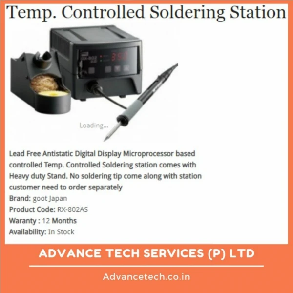
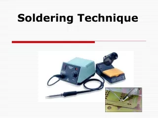
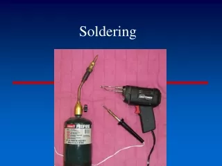
SOLDERING • SOLDERING IRONS • Basic elements • Resistance heating unit • Heater block 3 • Types of solder irons • Fixed heater • Temperature controlled by operator • Temperature controlled by built in magnetic switch • Operator controlled temperature sensor • Controlling heat at the solder joint • Relative thermal mass vs. heat cycle • Single pad - little mass • Double sided pad with plate through holes • Multi-layer boards • Lead mass - Temperature rise is relative to tip mass vs. work mass (Not tip temperature) • Terminal mass
SOLDERING • Reservoir size • Recovery rate (Ability to sustain heat - like a reservoir) • Block size (Heating reservoir) • Wattage - heating element • If more heat is needed at the joint, use a larger tip and/or increase the core capacity • Surface condition of pads or leads • Oxides and contaminants • Cannot create good solder joint on dirty surface • Clean surface before soldering • Use abrasive stick (eraser)
SOLDERING • Thermal linkage • Area of contact between iron tip and work • Apply solder between tip and work piece to create and increase thermal linkage and speed up heat transfer • (The secret of craftsmanship) • The reaction of the work piece to the work actions being performed on it (in soldering - heat rate recognition) • It is in the sensing of the change by sight, sound, smell and touch • In soldering the primary indicator is heat rate recognition • If tip is too large and too hot - heat rate too fast • If tip is small - heat rate too slow (mush melt) • Get in and out as fast as you can • Using the hottest iron available you should spend no more than 1-2 seconds on a particular joint being soldered, to prevent damage • The key work piece indicator for soldering, therefore, is sight.
SOLDERING • Selecting and handling the soldering iron • 30 watt pencil type with changeable tips is a good general purpose iron for electronic soldering • Unplated tips - copper type • Plated tips - iron type • Fully insert the and tighten the tip • Tin unplated tip when not using • Before using soldering iron, wipe tip off on a damp sponge to "shock off' (remove) any oxides • Always store iron in holder ("cubby") when not in use
SOLDERING • SOLDER JOINTS • Acceptable straight through lead • Length of wire above pad = radius of pad • Smooth surface • Feathered out smoothly to the edge • No pits or holes • No evidence of flux or flux pockets • Surface bright and shiny, free of any lumps • Slightly concave, with minimum amount of solder needed to make the connection
SOLDERING • Acceptable clinched lead • Length of wire = diameter of pad • Shape of wire apparent beneath solder • Smooth surface • Well feathered out to the edge • No pits or holes • No evidence of flux • Surface bright and shiny • Slightly concave
SOLDERING • COMPONENT SOLDERING - AXIAL LEAD (RESISTORS) • Clean component leads and solder pads • With abrasive stick • Then with solvent (alcohol) • Bend component leads • Use Conform tool • Clean again with solvent (alcohol)
SOLDERING • Insertion - clenched lead • Cut lead one pad diameter exposed beyond insertion hole • Press (bend) exposed end of lead flat against circuit board (with component fully inserted and flat against other side of board). • Soldering: (after flux application) • Touch the joint first (position so as to make solder bridge between component lead and pad). • Soldering tip contacts the lead • Paint the solder onto the joint, while moving the tip • Sweep the end of the lead last • Inspect your work !
SOLDERING • Unacceptable solder joints • joint • Too little heat applied • There is still a quantity of solidified flux between wire and terminal • joint • Heat withdrawn too soon, solder does not become liquid • Solder beaded up and may also show peaks • joint • Movement of wire during solidification, ,before solder cools • Looks frosty, dull, rough, granulated and may show cracks • joint • Repeated effort to reheat joint that will not properly wet due to contamination or lack of sufficient flux • It is chalky, dull or crystalline in appearance, and may show pitting on the surface
SOLDERING • TERMINALS • Terminal • Wrap of wire can be 180°, 270°, or 360° • Entry location • If only one wire, it is placed in the lower section, flat down against base • Two wires come in from same direction and are stacked • Insulation gap - one to two times wire diameter is permissible
SOLDERING • Terminal • Used to attach wire to circuit board • Resistance soldering tool • Useful in close quarters / limited lateral space • Electrodes can be positioned when cold • No danger of heating wrong area • Turn off power to tool to avoid arcing • Wire can enter from side, top and bottom • Wrap may be 90° or 180°
SOLDERING • Types of Terminals • Hook Terminal • Found on hermetically sealed relays • Wire wrap normally 90°, for repair work 270° recommended • Pierced Terminal • Has hole or eye • Wrap of wire 90° to 270°
SOLDERING • WIRE STRIPPERS • Mechanical stripper • Clean strip without deforming or nicking wire • Must use correct stripper notches • V-notch stripper • Blades do not conform to wire • Easy to nick wire • Thermal Stripper • Best method • Heat tips to melt or soften insulation and rotate lead, then pull off insulation prevents nicking of wire • Can be used for PVC (low temp) or Teflon (high temp) insulation