Download
1 / 21
1.63k likes | 3.4k Views
Soldering Basics. Overview. Introduction Definition Equipment Procedure Preparation Execution Finishing Specific Techniques Desoldering Tinning Conclusion References. Introduction – Definition. Unite two base metal items Add filler metal ( solder )

E N D
Overview • Introduction • Definition • Equipment • Procedure • Preparation • Execution • Finishing • Specific Techniques • Desoldering • Tinning • Conclusion • References
Introduction – Definition • Unite two base metal items • Add filler metal (solder) • Typ. < 842°F (450°C) melting point • Metal flows via capillary action • Metal bonds via wetting action • Metallurgical joint exhibits • Fair mechanical strength • Excellent electrical conductivity • Watertightness
Introduction – Common Usage • Electronics • Plumbing • Stained glasswork • Jewelry • Orthodontics
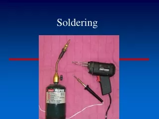
Introduction – Equipment • Solder • Joint filler metal • Metallic alloy • Sn/Pb • Typ. 60/40 or 63/37 mix • 60/40 melts @ 374°F (190°C) • 60/40 melts @ 364°F (183°C) • Pb-free • EU RoHS compliance • Typ. Sn/Ag/Cu alloy • Melts @ 422–433°F (217–223°C)
Introduction – Equipment • Flux • Removes base, filler metal oxides • Aids wetting process • Rosin-based flux • Availability • Separate paste • Flux-in-core solder • Primary fume component…
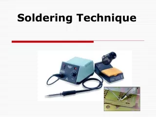
Introduction – Equipment • Soldering Iron • Solder melting heat source • Power rating • Higher power ≠ higher tip temp • Higher power heat larger joints • 15-35W for electronic work • Various tips available • Conical, chisel types • Tip width ~ 70-90% contact width • Never use ‘cold heat’ irons on electronics!
Introduction – Equipment • Solder wick • Braided copper strands • Flux impregnated • Absorbs solder when heated • Remove excess solder • Desolder components • Solder stand + sponge • Always return iron when unused • Always clean tip • Remove burnt flux • Remove excess solder
Introduction – Equipment • Heat sink • Protect heat sensitive components • Clip between component body and iron • Substitution • alligator clips • Hemostat • 99% alcohol + brush • Clean joint residual flux • Purity important
Procedure – Preparation • Clean components • Remove dirt, grease, oxidation • Causes unwettability • Solder tend to bead up • Component leads bright, shiny • Solder pads bright copper color • Fine steel wool, emery cloth
Procedure – Preparation • Prepare iron • Plug in iron • Dampen sponge • Clean tip w/ sponge • Apply solder to iron tip (tinning) • Wipe excess solder • Tip should be have silvery sheen
Procedure – Execution • Place component • Bend leads to fit hole pattern • Insert component through correct holes • Clinch leads slightly outward to hold in place • Attach heat sink if needed
Procedure – Execution • Solder component • Wipe iron w/ sponge • Apply tiny solder amount to iron tip • Not solder to form joint • Helps conduct heat properly • Touch tip side to BOTH pad and lead • Add bit more solder to form heat bridge • Wait for joint to be heated (~1-2 sec)
Procedure – Execution • Solder component (cont.) • Feed small solder amount from opposite side • Molten solder should spread and fill joint • Move solder away first • Move iron away quickly • Return iron to stand • Entire process ≤ 5 sec • Wait additional 3-5 sec for joint cooling
Procedure – Inspection • Inspect joint quality • Good joint • Shiny • Bright • Smooth • Concave solder fillet • Good wetting
Procedure – Inspection • Inspect joint quality (cont.) • Bad joints • Balled up or spiked • Dull color • Crystalline or grainy looking • Convex solder fillet • Dewetted • Causes • Dirty leads, pads • Movement during cooling • Overheating
Procedure – Finishing • Return iron to stand • Cut excess lead length • Clean residual flux w/ alcohol • Prevent future oxidation • Prevent unwanted electrical shorts
Techniques - Desoldering • Repair bad joints • Remove solder bridges • Excess solder connects two pads, leads • Unwanted electrical connection formed • Remove components • Both require old solder removal • Place solder wick against solder joint • Heat wick opposite side from joint • Solder should wick up braid • Remove braid first • Remove and return iron to stand
Techniques – Wire Tinning • Must tin wires before soldering to components, board • Attach heat sink just below insulation • Heat wire end • Touch solder to wire opposite iron tip • Solder should wick up wire • Too much heat damages wire insulation
Conclusion • Introduction • Definition • Equipment • Procedure • Preparation • Execution • Finishing • Specific Techniques • Desoldering • Tinning
References • www.curiousinventor.com/guides/How_To_Solder • www.aaroncake.net/electronics/solder.htm • www.qsl.net/n9zia/solder.html • www.solderinguide.com • itp.nyu.edu/physcomp/Tutorials/SolderingAPerfBoard • www.modchipworld.co.uk • www.drmsmetals.com/data/electronic/erzin.html • www.hsl.gov.uk/capabilities/rosin.htm • www.sparkfun.com • www.howardelectronics.com • www.ladyada.net • www.uelectronics.info • us.geocities.com/steves_workshop • www.theavenuestaineglass.com