Download
1 / 29
300 likes | 511 Views
H-Jet Polarimeter Upgrades & Status. BNL: A. Bravar, G. Bunce, R. Gill , Z. Li. A. Khodinov, A. Kponou , Y. Makdisi , W. Meng, A. Nass, S. Resica, A. Zelenski , V. Zubets WISCONSIN: T. Wise , M.A. Chapman, W. Haeberli Kyoto: H. Okada, N. Saito ITEP-Moscow: I. Alekseev, D. Svirida

E N D
H-Jet Polarimeter Upgrades & Status BNL: A. Bravar, G. Bunce, R. Gill, Z. Li. A. Khodinov, A. Kponou, Y. Makdisi, W. Meng, A. Nass, S. Resica, A. Zelenski, V. Zubets WISCONSIN:T. Wise, M.A. Chapman, W. Haeberli Kyoto: H. Okada, N. Saito ITEP-Moscow:I. Alekseev, D. Svirida IUCF: E. Stephenson Rikkyo U.: K. Kurita Data analysis: H.Okada, O. Eyser, K. Boyle Yousef Makdisi Collider-Accelerator Department, BNL Spin 2006
ASSEMBLED JET DISSOCIATOR 6-POLE MAGNETS RF TRANSITIONS TARGET MAGNET COILS RHIC BEAMS RECOIL DETECTORS BRP POLARIMETER
y x jet Oleg Eyser The Jet Polarimeter 96 silicon strips: (6 x 2 x 8) geometry reflectskinematics of elastic ppscattering 5 cm displacement of beams 8 cm ~ 80 cm
Atomic beam intensity and density measurements in the collision region • H-beam intensity and density vs. H2 flow in dissociator.
Jet Operating Parameters • Stable behavior over the `04, `05 runs, `06 run is similar • `06 we ran typically with 55 sccm H2, .25 sccm O2 • P+ = 0.957±0.001 and Pˉ = -0.959±0.001 • Intensity 12.4 x10¹⁶ Atoms/sec • Thickness along the beam1.3±0.2 x 10¹²Atoms/cm2 • Added A/C to the RF and Power Supplies for stability • After a nozzle cleaning, the intensity starts at 0.5-.6 of maximum, rises to maximum in about 1 day, flat for 12 days, and decreases slowly to blockage in 2 weeks. • Changed the beam beta* from 5 to 10 meters in an attempt to reduce background.
H2 and H2O dilution • Sample Jet with 600 eV Electron Beam • Extract Ions and Momentum analyze • Correct for cross-section PRELIMINARY Mass 1 H2 dilution is (2.3±1.2)% during normal running conditions H2O dilution is small but measurable: (0.15±0.05)% Mass 2
Total target polarization Assume only the H in H2O contributes because of Fermi motion of oxygen nuclei ATOMS ARE DILUTED BY: (2.3±1.2)% H2 and (0.15±0.05)% H2O PRELIMINARY P+JET = 0.933±0.013 P-JET = 0.935±0.013 Instability and problems determining the proper cross sections Thus still use the QMA results. 92.4% +/- 0.2 %
RHIC Jet Beam Profile Imaging SystemS. Bellavia, D. Gasner, D. Trbojevic, T. Tsang, A Zelenski Camera Filter Wheel UpperBox Secondary Lens Doublet MotionStage MirrorBox PrimaryLens Mirror box If successful, could provide in situ H and H2 monitoring
Beam in the Cage Camera Focus on Beam Camera Focus on Far Wires Camera Focus on Near Wires
FWHM (x) = 4.5 mm RHIC Yellow beam profileafter 656 nm red filterData of Feb 28, 2006 σ(x) = 1.91 mm FWHM (x) = 6.4 mm } H-jet Width σ(x) = 2.7 mm • 486 nm filter: H-β line • gives similar result • Expect to see molecular • hydrogen in a broad band • around 350 nm. • A 320 nm filter shows no • jet image. • Tsang: May need a camera • sensitive to far IR to detect this! FWHM (y) = 1.9 mm } RHIC beam σ(y) = 0.8 mm
Depolarizing Resonance Scan with 112 bunches • Nass reported (Spin 2004) no depolarizing resonance effects on the Jet polarization with 60 bunches in the RHIC beam. • We conducted a resonance scan using the "flip in" method.Conditions: ABS SF transition ON BRP WF transition ONBeam intensity total ~120x1011 protons, ~1.1x10¹¹/bunch • The scan took about 1 hour and during that time blue beam decayed to ~103x1011 protons. • Scanned the Inner and Outer holding field coil currents from 319.8 inner/252.0 outer to 356.6/281.0 amps respectively in 69 steps.This range guarantees at least one 1-2 resonance but most likely two resonances (harmonic numbers 59 and 60) • We observed no resonances across the entire scan at a level 1x10⁻³ • The JET required a field uniformity over a 3 cm gap of 6ּ10-3 what was achieved is 5ּ10-3
`06 Jet Vacuum W/ NEG coating
Jet operations in `06 • New code to readout the full waveform along with a new versatile monitoring program. (Alekseev and Svirida) • Daily PC and DAQ technical support and monitoring (Gill) • Jet oversight and maintenance (Zelenski and Makdisi) • The SFT RF acted up (Wise: rescue increase gain) • Replaced the dissociator nozzle midway. • MCR Operators took full responsibility and saw to it that data were collected in each fill. • Attempted to collect data with both beams vertically separated failed due to loss of acceptance. • Horizontally separated beams: not acceptable as the beams have to cross and exacerbate the beam-beam problem.
Waveforms(new H-Jet data format this year) Fit Half maximum Baseline = 8
Snap shot of online Monitoring Blue Beam background Yellow Beam hitting the jet
Click on Info to get statistics With 112 bunch fills and high intensities per bunch on average the jet collects enough statistics (online) to measure the beam to jet polarization ratio to better than 10% per 7-8 hour fill. Offline analysis is required to see how much data are lost to attain The signal to background ratio.
Data Collected @ 100 GeV Fills Dates Beam Events 7630-7652 3/18-25 B 2.5M 7662-7697 3/26-4/4 Y 2.8M 7718-7745 4/4-11 B 1.6M 4/11 Lost Si detector # 3 7780-7802 4/12-5/2 Y 3.8M 7810-7858 5/3-15 B 4.2M 7887-7946 5/19-6/1 Y 2.5M 6/2 Si detector #1 acted up: reduced the bias from 200 – 175 V. 7949-8002 6/3-5 B 2.0M
Data Collected at 31.2 GeV Fills Dates Beam Events 8005-8054 6/9-17 B 3.6M 8055-8061 6/18-20 Y 2.6M The Fills were relatively shorter durations. The statistics will allow a good calibration of the p-CNI polarimeters near injection.
Data Analysis • The 2004, 100 GeV data AN and ANN were published H. Okada et al. PLB 638 (2006). • The 2004, 24 GeV analysis (15 hours) AN and ANN is complete (Hiromi Okada). Calibration of the Blue pC polarimeter at injection. • The `05 data is complete (Oleg Eyser). • The 31.2 GeV data a good statistical sample taken in conjunction with the polarimeters (Oleg Eyser). • The 100 GeV `06 to be analyzed (Kieran Boyle). • The Jet has met its goal to provide the necessary polarimeter calibration to the desired level of 3% • A remaining issue is the ability to process the data off line on a timely basis.
What is next? • Determine the cause of the silicon failure. • Replaced the failed detectors with existing spares. We are experiencing high currents in the new detectors. • Placed an order with Hamamatsu for 12 new detectors. • Started the procurement of spare 25 Wave Form Digitizer units for jet and polarimeters. • Look into increasing the acceptance to be able to measure both beams simultaneously (not so easy) • As and R&D effort, T. Wise, Wisconsin is building two RF cavities to allow a polarized deuteron jet beam.
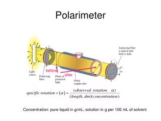
Setup of the JET • Atomic beam produced by expansion of a dissociated H beam through a cold nozzle into vacuum chamber • Nuclear polarization achieved by HFT’s (SFT, WFT) after focusing with sextupole magnets • After passing RHIC beam BRP sextupoles focus the atomic beam into the detector • Determination of the efficiencies of these HFT’s and the polarization of the beam by comparing the detector signals while running different HFT’s, e.g.: • ABS SFT • ABS WFT • ABS SFT + ABS WFT • BRP HFT’s for calibration
Depolarizing Effects • Beam induced depolarization due to bunched structure of p-beam transient magnetic fields transverse to the beam direction • Closely spaced depolarizing resonances in the usable range of the surrounding target holding field • High uniformity of the target holding field necessary Required at JET: DB/B=6ּ10-3 achieved 5ּ10-3 No depolarization with 60 bunches in RHIC Toms theoretical values to be added
Operational issues • Nozzle blockage frequency: every two weeks. It takes 3 hours to warm up, ½ hour beam down, and two hours to cool down and back online. • Slower intensity ramp up than before. 3-4 days to reach full intensity, plateau for a few days and then a slow decrease to blockage. • Midway replaced the nozzle which improved matters somewhat. • The SFT phase became unstable for a period. Fixed by T. Wise by increasing the gain. • Lost some precious time due to memory full condition. • Lost one silicon detector, and another acted up.
Operations continued • Failed to take data with two beams at the same time: • Requirement that the two beams be separated by 4-6 mm. • The vertical collimation occluded the silicon acceptance. • Determined no polarization loss with 112 bunch operation and 1.1011 p/bunch implying the holding field uniformity is adequate. • Installed a CCD camera to look at light emitted as the beam hits the jet. This serves as another vertical beam emittance device. Our interest is to measure the molecular hydrogen contamination. • No pump failure this run.