Download

1 / 72
820 likes | 1.22k Views
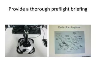
HSL 41 Preflight. Preflight “Gouge”. This is a guide to assist you in you preflight and identification of components. This is not a substitute of NATOPS. OBJECTIVES. Preflight Requirements What to look for CAUTIONS, WARNINGS, & NOTES. BEFORE YOU START.

E N D
Preflight “Gouge” • This is a guide to assist you in you preflight and identification of components. • This is not a substitute of NATOPS.
OBJECTIVES • Preflight Requirements • What to look for • CAUTIONS, WARNINGS, & NOTES
BEFORE YOU START... • Thoroughly check the ADB (Aircraft Discrepancy Book) • Are the Daily and Turnaround Inspections properly completed and up to date? • Fuel Samples? Oil Consumption? • Are there any gripes that catch your eye?
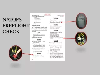
NATOPS CHAPTER 7 • 7.2 PREFLIGHT • Prior to flight, the pilot in command shall ensure that a complete visual check of the helicopter has been conducted. • The aircrew preflight inspection may be divided among pilot, ATO, and Sensor Operator.
PREFLIGHT YOUR EQUIPMENT • Flight Suit (dog tags?) • Make sure you are FOD free • Helmet • Lip light? Clean Visors? • Gloves • No holes • Flashlight
NATOPS CHECKLIST • Use NATOPS checklist items as a minimum. • Preflight with other HACs and ask questions! • Talk to other pilots, aircrew, and maintainers for what they look for. • Perform a daily and turnaround to see what our maintainers are looking for. • Inspect with extra concern areas that have recently been worked on or that have outstanding or recurring gripes in the ADB.
GETTING STARTED • Initial walk around • Look at the aircraft for anything that looks out of place. • “Man, that just ain’t right!” • Are tie downs, plugs, and covers still installed? • Leakage • Is there any noticeable oil or fuel on the ground? • Is fluid running down the side, underside, or tail?
WHEN IN DOUBT • If something doesn’t look right, ask! • To call a troubleshooter use (DEMOT): Make a “T” signal with both hands followed by a number. T-1 = AD, T-2 = AE, T-3 = AM, T-4 = AO, T-5 = AT AD AE AM AO AT
DOWNING AN AIRCRAFT • If you don’t feel it is safe, don’t fly it! • Maintenance Control can tell you if a gripe is up or down by checking the MIM’s (Maintenance Instruction Manuals). • QA is always there to help. • Make sure the question is answered to your satisfaction!
PREFLIGHT….. NATOPS ITEMS ADDITIONAL ITEMS
Seat Harness ELT Seat Track
FLIR HCU Flight Controls
Wave Guide Bottles Selector Valve WPS- Select A or B Radar Pressure Pop out
Nose Bay Door Seal Windshield Wipers TACAN Antenna Temperature Sensors KIT 1C Mount UHF 2 Laser Enable/ Disable, Gimble Switch Displacement Gyros NSIU Pitot Tube ECA FLIR Turret Unit AFCS RADOME ESM ACU Turn Rate Gyros Ground AAR-47 Data Link Antenna Search/Hover Lights ESM Antenna RADALT Antennas
Drive Shaft Covers Electrical Equipment Compartment Engine Exhaust APU Exhaust Gravity Refuel Water wash Static Ports ESM Antenna SO Window Sonobuoy Launcher WOW Switch Door Pylons and Stores Pressure Refuel Avionics Cooling Exhaust Fire Extinguisher Thermal Plug Anticollision Light Ext ICS Arm Panel Position Light Sonobuoy Antenna
Strut Brake Lines Grounding Wire (Hidden) Brake PUK Indicators Tire Condition
Lock Lever in unlocked position. Check up in locked position. Strut Condition Grounding Wire Tire Condition Shimmy Dampner Tail Grounding Wire Slip Marks Tail Probe
Lower Anti-collision Light Data Link Antenna UHF/TACAN Antenna Block I, UHF/VHF/TACAN Antenna
Pylon Fold Hinges Lockpin Keeper
Oil Cap IGB Cowling Cap Lock Oil Level
Stab Lockpins Keeper Tail Bumper
Stabilator Isolator Mount Position Sensor Arm Actuator Arm/Rod Forward Spar Forward Spar Web
Anti Collision Light Position Light AAR-47 Stab Position Link Stab Actuator Static Wicks
De-Ice Harness Pitch Change Links Bonding Wire Indexer Retracted Pitch Change Shaft Pitch Beam Tail Rotor Blades
TGB Oil Cap Balancing Weight Location TGB Cowling Pitch Beam Retainer Nut
Anti-collision Light (Note: screw installed in top of upper light, not installed on lower light, to allow water to drain) Tail Rotor Spring Cylinders Blade Boot Tail Rotor Quadrant Flexible “Thomas” Coupling Tail Rotor Servo Number 6 Driveshaft Centering Springs Hydraulic Lines Cable and Pulley (each side of Quadrant)
Tail Rotor - Cont. Pitch Beam Retainer Nut Index Actuator Indexer shown in extended position. Check retracted Pitch Change Beam Blade De-ice Connector Pitch Change Shaft
Abrasion strips and de-ice boots TGB Oil Level T/R Tip Cap
Disconnect Jaws Tail Driveshaft Disconnect Spring Thomas Coupling Viscous Damper
Undersideof blades 6 5 4 Critical Fasteners
Transition Section Tail Cone (Thermal Barrier removed) Accumulator Dump Valve Tail Strut APU Accumulator ECS Duct Looking forward, above fuel cell Premature Breakaway Indicator Fuel Lines & Breakaway valves Dehydrator Kit Doppler Antenna (under platform)
Ice Detector (hidden) ECS Exhaust Rescue Hoist Avionics Cooling Inlet Mirror HF Antenna ECS Intake Cabin Door Float bag Fairing MAD Reeling Machine and Towed Body Pylon and Stores Main Landing Gear Drag Beam External Power Receptacle Access
Sono Launcher Bottle RAST Backup Messenger Cable Distributor Lock First Aid Kit Crash Axe Hoist Pendant Fire Extinguisher RAST Equipment Sono Launcher Selector Valve APU Pump Handle
Cabin APU Accumulator Pump (manual) HIFR Pressure Gauge APU Accumulator Pressure Gauge HIFR Go-No-Go Filter ECS Duct APU Pump Handle APU Accumulator Nitrogen Charge APU ESU
APU Accumulator Min 2650 PSI Winterization Kit Xsmn PDI
Hover Grip Rescue Station Hoist Shear Cover RAST Manual Release RAST Machine ICS cord Fire Extinguisher Hoist Pendant RAST Reeling Machine First Aid Kit Ratchet Canteen NATOPS
Hydraulics Bay - cont. Yaw Trim Servo Back-up Hydraulic Pump Collective Trim Servo Roll Trim Servo Pitch Bias Actuator (PBA) Pitch Trim Servo Avionics Cooling Inlet Pressure Reducer Failure Indicator
Hydraulics Bay - cont. SAS Actuator Boost Servo SAS Retaining Nut Redundant Link Forward
Hydraulics Bay - cont. Torque Shaft Lever Upper Support Bearings (under boots)
Hydraulics Bay - Cont. Back-up Pump Motor No. 1 Transfer Module Lateral Primary Servo Aft Primary Servo Blade Fold Transducers Mixing Assembly/Unit Imperfect Threads Forward Primary Servo
Hydraulics Bay - Cont. #2 AC Generator “Coffee Can” Hydraulic Reservoir Accessory Module #2 Hydraulic Pump Quick Disconnects Hydraulic Selector Valve Filter Bypass Popout Buttons Bleed valve Check for: Temperature Dots Mated white paint stripe Roll pin and safety wire Hydraulic Transfer Module Load Demand Spindle (LDS) Cable
Main Rotor Head Hydraulic Damper Hose BIFILAR Absorber Weight Blade Lockpin Pullers (pins, 2 per blade, shown retracted into housing) Pitch Lock Motor Pitch Horn Pitch Lockpin PCR Elastomeric Bearing Droop Stop Damper Pitch Change Rod (PCR) Droop Stop Heater Connector
Thrust Elastomeric Bearing (viewed through hub cutouts with mirror) Main Rotor Head - cont. Anti-flap Cam Spherical Elastomeric Bearing (backside viewed through hub cutouts using mirror BIM Indicator
Pitch Lock Pins Main Rotor Blade Elastomeric Bearing BIFILAR Absorber Weight
Balance Weight Attachment Arm Blade Fold Lock Pins Top of Blades Anti-Flap Stop BIM Indicator Blade Fold Motor
Main Rotor Hub Assembly Damper Anti-Flap Stop Pitch Change Horn Pitch Lock Actuator Droop Stop Heated Droop Stop Harness PCRs
Accumulator Pressure 1200 PSI minimum