Download
1 / 64
750 likes | 1.66k Views
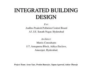
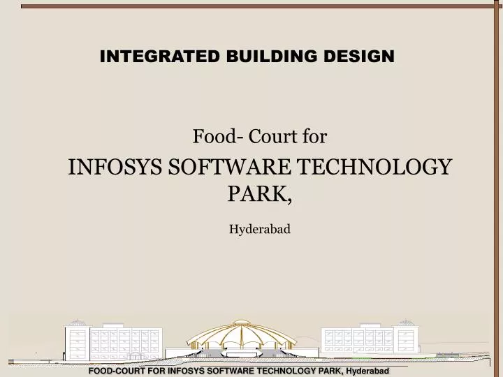
INTEGRATED BUILDING DESIGN. Food- Court for INFOSYS SOFTWARE TECHNOLOGY PARK, Hyderabad. WHO’Z WHO …. Client : Infosys Technologies Ltd. Hyderabad. Architect : M/s Sundaram Architects Pvt. Ltd. Bangalore. Contractors : CCCL, Chennai

E N D
INTEGRATED BUILDING DESIGN Food- Court for INFOSYS SOFTWARE TECHNOLOGY PARK, Hyderabad
WHO’Z WHO … Client: Infosys Technologies Ltd. Hyderabad. Architect: M/s Sundaram Architects Pvt. Ltd. Bangalore. Contractors: CCCL, Chennai Project Review Group: Amit Asawari Ashwini Bharat Debarshi Manish Milind Suvojit
Project Summary Infosys Software Tech Park , Hyderabad in brief: A corporate Building 11 Software Blocks Food court + Recreation center + Auditorium Service Block Residential Block
Our focus… Food- court + Recreation center Why ? • Unique structure • Extensive scope of services • Innovative dual functionality of the space
Features… FOOD COURT Multipurpose hall Bank ATM AHU room Electrical Room Toilets, Dormitories Podium Level Upper level Food-court / Auditorium capacity 600 people Dormitories Shop Gymnasium Aerobics center Indoor-games space Kitchen e- kiosk.
Podium level Plan Foodcourt/ auditorium Plan
Section Thru the Structure Site Section
Thrust Areas… Structures Services Management
Deliverables till 20th. Total Deliverables: Structures • Vault (shell) structural analysis Ansys • Column Design and analysis • Beam Design and analysis • Slab Design and analysis ( All Designs in STAAD, Analysis in STAAD and ANSYS) • Design and Analysis of beam component of the structure • ANSYS and STAAD will be used for beam analysis
Total Deliverables: Services • HVAC Heat load simulation using Energy Plus Optimization using GenOpt, Design and Layout of Air conditioning services. • Lighting Lighting Simulation using Radiance Design of lighting Scheme and layout. Selection of luminaries • Electrical Calculation of load Design of wiring network.
Kitchen • Design of Kitchen layout • Design of services (steam lines, hot/cold, gas) • Acoustics • Calculation of reverb time • Suggestion/design of requisite fitting to bring R.T to the desired level, Modeling and simulation . • Fire simulation • Design /planning of detecting and fire fighting systems • Overall scheme • Simulation in FDS • Security • General plan of security arrangement, devices, systems.
Water supply • Calculation of loads • Layout and design • Networking • Layout design • Automation • Automation of the required services
Deliverables till 20th. • HVAC :Simulated results of heating loads in Energy Plus • Lighting:Simulation of lighting using Radiance • Fire Simulation:Layout of Sprinklers, Detectors. • Security:Basic Plan of the proposed security layout • Walk-thru: 3D modeling and walk-thru using 3D max
Total Deliverables: Project Management • Management Information Systems-Project level • Safety Planning. • Estimation • Tendering • Contract Management. • Project Planning • Quality Assurance and Quality Control. • Disaster Management-Execution of Project.
Deliverables till 20th. Management Information System • Organization chart for the site. • Flow of information • Identify various agencies likely to be involved on site. Safety Planning • Develop guidelines for safety during construction on site.(any two levels of the organization at site under discussion). Quality Assurance and Quality Control • Develop guidelines for quality assurance and control on site(at any two levels of the organization at site under discussion).
Structural Modeling and AnalysisSubmitted ByAmit Kumar Saran(Roll No. – 01)Ashwini Kumar (Roll No. – 05) Bharat Sondhi (Roll No. – 06)
Details of The Model Analyzed as a Space Frame Structure using STAAD – III package. Total No. of Joints : 388 Total No. of Members/elements : 548 Total No. of Supports : 56 Total No. of Degrees of Freedom : 1992 Original Bandwidth : 358 Reduce Bandwidth : 16 Size of Stiffness Matrix : 179280
Modeling Ring Beam in the Structure is modeled as a set of straight line elements. Ring Beam is broken into straight beam at an interval of 5.625 degrees. Structure is analyzed for Self weight, Live Load, Wind Laod, Earthquake Load.
Assumed Loading as per IS Codes Unit Weight of Concrete : 25 KN / m3 Unit Weight of 200 thick solid Concrete Block Wall : 24 KN / m3 Floor Finish : 1.0 KN / m2 Live Load at Type Floor : 3.5 KN / m2 Live Load at Roof Level : 1.5 KN / m2
Wind Load Analysis Design Wind Speed = Vb * k1 * k2 * k3 where Vb = Basic Wind Speed in m / s. k1 = Risk Coefficient = .91 k2 = THS Factor =1.02 k3 = Topography Factor = 1 Vb = 44 m / s for Hyderabad Terrain Category : 2(Open terrain with scattered obstructions of height between 1.5m to 10m) Class of Building : B(Structures having max. dimensions between 20m to 40m)
Wind Intensities Design Wind Pressure = 0.6 Vz2 All Data is from IS – 875 ( Part – 3 ) – 1987 Exposure Factor At all Joints : 1 At 1st Floor : 1.0008 KN / m2
Wind Load Analysis The wind load on a building shall be calculated for the building as a whole. Wind Load on the Building = Cf * Ae * Pd where Cf = Force Coefficient Ae = Effective Frontal Area Pd = Design Wind Pressure The value of Cf is 0.5 from Table – 23 of IS : 875 ( Part – 3 ) for buildings of circular shape. Wind Load at each floor is distributed among the columns at that floor accordingly their relative stiffness.
Earthquake Design Consideration The Building will be designed for horizontal seismic force only. The Structure is analyzed as an equivalent static approach employing the use of a Seismic Coefficient Method.
Terminology Basic Seismic Coefficient ( α0 ) To give the basic design acceleration as a fraction of the acceleration due to gravity. Importance Factor ( I ) To modify the basic seismic coefficient and seismic zone factor, depending upon the importance of structure Soil Foundation System Factor ( β ) To modify the α0 and seismic zone factor, depending upon soil foundation system. Design Horizontal Seismic Coefficient ( αh ) Seismic coefficient taken for Design.
Earthquake Load Consideration Earthquake Zone ( Hyderabad ) : II Basic Horizontal Seismic Coefficient ( α0 ) : 0.01 Coefficient depends upon soil foundation system ( β )( Hard Soil ) : 1.0 Importance Factor ( I ) : 1.5 Design Value of Horizontal Seismic Coefficient, αh = β * I * α0 = 0.015
Base Shear Calculation The Base Shear is given by, Vb = K * C * αh * W Where K = Performance Factor according to structural framing system = 1 C = Coefficient defining the flexibility of structure depends upon the no. of storeys in structure = 0.75 αh = Design Seismic Coefficient W = Total DL + 25 % of LL
Base Shear Calculation and It’s Distribution among Floors Base Shear, Vb = K * C * αh * W = 1 * 0.62 * 0.04 *1947.2 = 482.9152 KN The distribution of forces along with the height of the building is given by, Qi = Vb * ( Wi * hi2 ) / Σ ( Wi * hi2 )
Nodal Forces and Seismic Shear Forces At Various LevelsQi = Wi hi2/ Σ ( Wi * hi2 )
Possible Load Combinations ( Dead Load + Live Load ) * FoS ( Dead Load + Live Load + Wind Load ) * FoS ( Dead Load + Live Load + Earthquake Load ) * FoS For 1st case FoS will be 1.5 and for the rest of the case FoS will be 1.2 as per IS – 456.
Shear Force and Bending Moment Maximum Shear Force = 930.20 KN Maximum Bending moment = 2079.17 KNm Maximum Deflection = 24 mm
Failure ZoneGreen(Safe),Yellow(Moderate Failure),Red(Extreme Failure)