Download
1 / 114
1.76k likes | 3.3k Views
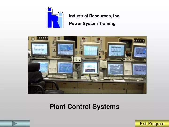
Plant Control Systems. Industrial Resources, Inc. Power System Training. In this module we will:. Describe the typical Distributed Control System capabilities. Describe how power plant processes are accessed and controlled from the DCS controllers.

E N D
Plant Control Systems Industrial Resources, Inc. Power System Training
In this module we will: • Describe the typical Distributed Control System capabilities. • Describe how power plant processes are accessed and controlled from the DCS controllers. • Describe how DCS control system diagrams are used to interpret control system loops. • Describe basic Unit loading and control features. This presentation is designed to provide you the information you need to understand and operate the Distributed Control System. You should view all slides and read and study the information presented.
MAIN MENU To Start, Click on one of the buttons below You Should Start The Program In The System Function Section. System Function Process Control Control Diagrams Work Stations Unit Control Review Questions Review Questions Review Questions Review Questions Review Questions If you exit the program and want to re-start at a different section or want to see the review questions, click on the appropriate button.
The Distributive Control System controls plant systems and equipment. Motors Valves Steam Turbine Generator and Exciter
Plant Control System Overview The DCS System collects and stores three (3) types of data received from plant processes: • Analog data • Digital data • Calculated data
Analog Data Temperature Transducer Flow Transducer Pressure Transducer
Valve Closed Valves Open Digital Data Motors “ON” Motor “OFF” Limit Switch
Water Temperature AIN PID Water Flow Valve Position Signal AIN PID AOUT Temperature/Density Compensated Water Flow Compound Calculated Values
CRT Alarms Alarms
Historical Data Retrieval Deaerator Storage Tank Level Trend
Work Station Work Station
Work Station CRTs (Monitors) Trackball Keyboard and Annunciator Keypad
Types of Displays Several types of displays are accessible from the control system. These include: • P&ID Displays • Motor Control Displays • Process Control Displays
Process Control Displays Measured Bias Output
Review Questions What three types of data received from plant processes are collected and stored by the DCS? What is the typical origin of Analog data? What is the function of the “node” bus? Which type system display represents system piping and instrumentation? Review Review Review Review
Control Loops Include: • Measured Variable (MEAS) • Sensor • Controller • Final Control element.
Relay Control Start/Stop Controls Open/Close Controls
Water Temperature AIN PID Water Flow Valve Position Signal AIN PID AOUT Control Loop Modulating Control Controller
DCS Control • Digital Signals (Zero and One) • Analog Signals (4 – 20 Ma) Two (2) types of control signals route to and from the DCS System Controller:
Computer Logic Blocks There are several types of logic blocks used to convert analog signals to digital signals for use by the DCS. These include: • AIN Block • AOUT Block • CIN Block • LLAG Block • PID Block
AIN Temperature Transducer AOUT Valve AIN and AOUT Blocks
CIN CIN Block Breakers
Gland Exhaust Fans Lead Lag (LL Block) Select A LLAG Select B
PID Block 3-element Drum Level Feedwater Flow Valve Position Signal PID Steam Flow Feedwater Master
Water Temperature AIN PID Water Flow Valve Position Signal AIN PID AOUT Temperature/Density Compensated Water Flow Compound Compounds
Review Questions What is process control? What is an Algorithm? What two (2) types of control signals route to and from the DCS System Controller? What is a Compound? Review Review Review Review
Control Diagrams • Control system component arrangement • Control system component function indicating the signal conditioning • Operating characteristics of the control system • Operator interface devices • Setpoints, transfer points, permissives, Alarms Control Diagrams provide the following types of information:
Control Diagram Symbols The following types of control symbols are found on Control Diagrams: • Transmitter and/or sensing elements • Final Control Element/Operator • Converters • Signal Processors
FT PT LT Pitot Tubes Flow Transmitter Pressure Transmitter Level Transmitter Level Sensors Sensing Elements and Symbols Pressure Transducer
Final Control Element Valve Positioner Damper Positioner Motor Controller Hydraulic Coupling Controller
Converters • Current to digital converter (I/D) • Thermocouple to digital converter (MV/D) • Resistance to digital converter (R/D) • Digital to current converter (D/I) • Current to pneumatic converter (I/P) • Contact to digital converter (C/D) • Digital to contact converter (D/C)
Signal Processors • Single digital input conversion true = 1 (CIN) • Digital input conversion true = 0 (CIN) not • Single analog input conversion (AIN) • Analog output conversion (AOUT)
Control Diagram Symbols Summer Comparator Multiplier Averaging
Control Diagram Symbols Proportional Controller Integral/Reset Controller Derivative Rate Controller Multi-function Segment Characterizer
Control Diagram Symbols Time Function Characterizer Bias Unit Signal Selector Signal Limiter
Control Diagram Symbols Transfer or Trip Relay Switch Manual Output Driver Analog Signal Generator
Logic Gates and Truth Tables • Building Blocks of Digital Logic • Most have 2 or more inputs • Operate in Binary • Low State is 0 Volts • High State is 5 Volts