Download
1 / 42
580 likes | 2.43k Views
Lab1 Scan-Chain Insertion And ATPG. Pro: Chia-Tso Chao TA: Szu-Pang Mu Hao-Wen Hsu 2011/5/26. Outline. Introduction Design Compiler TetraMax Lab. Outline. Introduction Design Compiler TetraMax Lab. Introduction. This lab compares impact on circuit after scan-chain insertion .

E N D
Lab1Scan-Chain Insertion And ATPG Pro: Chia-Tso Chao TA: Szu-Pang Mu Hao-Wen Hsu 2011/5/26
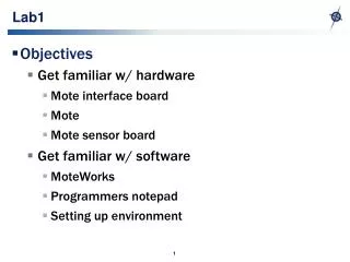
Outline • Introduction • Design Compiler • TetraMax • Lab
Outline • Introduction • Design Compiler • TetraMax • Lab
Introduction • This lab compares impact on circuit after scan-chain insertion. • Items being compared including area, power, test coverage, # of patterns. • Synopsys Design Compiler is the most common synthesis tool supports interactive command input. • Synopsys TetraMax is used to perform ATPG (Automatic Test Pattern Generation) and fault simulation.
3 8 6 5 4 2 7 1 Scan Synthesis Flow HDLCode Scan-Ready Synthesis Set ATE Configuration Pre-Scan Check Scan Specification Scan Preview Estimate Test coverage Scan Chain Synthesis Post-Scan Check
Fault Reports ATE Vectors Simulation Testbenches DFT compiler to TetraMax design_dft.v write –f verilog –hierarchy \–output “design_dft.v” read netlist design_dft.v TetraMax DC Simulation Library read netlist library.v design.stil write_test_protocol –out design.stil run drc design.stil
Outline • Introduction • Design Compiler • TetraMax • Lab
Work Stations • Using putty to connect. • Account: vlsitesting01~vlsitesting25 • Password: vlsi0testing1~vlsi2testing5 • Server IP • pc414-23.ee.nctu.edu.tw • pc414-24.ee.nctu.edu.tw • pc414-25.ee.nctu.edu.tw • pc414-26.ee.nctu.edu.tw
Setup Tool Environment • Defined in .synopsys_dc.setup (it’s a hidden file, so use command $ ls –al to find it) • set link_library "l90sprvt_typ.db" • set target_library "l90sprvt_typ.db" • set hdlin_translate_off_skip_text "TRUE" • set edifout_netlist_only "TRUE" • set verilogout_no_tri true • set plot_command {lpr -Plp}
Invoke Design Compiler • $ source /CAD/synopsys/CIC/synthesis.cshrc Just type above command for the first time invoke design compiler • $ cd lab1 • $ tar -zxvf lab1.tar.gz • $ dc_shell-t
Read File, Link, Uniquify • Read in RTL verilog source files • dc_shell> read_file -format verilog pre_norm.v • Show library details • dc_shell>list_lib • Specify the current module to sythesize • dc_shell> current_design pre_norm • pre_norm : top module • Link • Resolve the design reference based on reference names • Locate all design and library components, and connect them • dc_shell> link • Uniquify • Removes multiply-instantiated hierarchy in the current design by creating a unique design for each cell instance • dc_shell> uniquify
Wire Model, Scan Style, Clock • Setup wire load model define in library • dc_shell> set_wire_load_model -name wl10 -library l90sprvt_typ • Use ‘report_lib l90sprvt_typ’ to view library information • Specify the scan style. Four styles are supported • 1) Multiplexed flip-flop (multiplexed_flip_flop) • 2) Clocked scan (clocked_scan) • 3) Level-sensitive scan design (lssd) • 4) Auxiliary-clock LSSD (aux_clock_lssd) • dc_shell> set_scan_configuration -style multiplexed_flip_flop • Specify clock • dc_shell> create_clock clk -period 10 • clk: the signal name define in the HDL file
Compile(1/2) • Using command “compile” to perform logic level and gate level synthesis and optimization on current design • “-map_effort” : specify the relative amount of CPU time spent during the mapping phase of compile
Compile(2/2) • “-scan” : specify command to consider the impact of scan insertion on mission mode constraints during optimization. This option causes the command to replace all sequential elements during optimization. Some scan-replaced sequential cells might be converted to nonscan cells later in the test synthesis process because of test design rule violations or explicit user specifications. • dc_shell> compile -scan -map_effort medium
Identify Scan-Chain Count, Generate Test Protocol(1/3) • Set scan-chain count considering the limitation of ATE or software, multiple clock domain, test time limitation • dc_shell> set_scan_configuration -chain_count 10 • Define clocks in your design, then generate a test protocol • infer_clock option to find clock signal • infer_async option to find reset signal • dc_shell> create_test_protocol -infer_clock -infer_async
Identify Scan-Chain Count, Generate Test Protocol(2/3) • If you want to specify some PI/POs to be normal inputs at operation mode and scan inputs during test mode use following commands • dc_shell> set_scan_configuration -chain_count 1 • dc_shell> set_dft_signal -port add -type scandatadin • dc_shell> set_dft_signal -port sign -type scandataout • dc_shell> create_test_protocol -infer_clock -infer_async
Identify Scan-Chain Count, Generate Test Protocol(3/3) • If you want to specify scan-chain order, user the following command • dc_shell> set_scan_configuration -chain_count 1 • dc_shell> set_scan_path scan_1 { DFF_2 DFF_3 … DFF_50 } • dc>shell> create_test_protocol -infer_clock -infer_async
Preview Design, Scan-Chain Synthesis • Preview the scan design • dc_shell> preview_dft • Check test design rules according to the scan style you chose • dc_shell> dft_drc • Insert scan chain • dc_shell> insert_dft
Report Area, Time, and Power • Report area, timing, and power • dc_shell> report_area • dc_shell> report_timing • dc_shell> report_power
Result(1/2) • Area • Number of ports: 147 • Number of nets: 637 • Number of cells: 490 • Number of references: 82 • Combinational area: 3023.452047 • Noncombinational area: 1302.566048 • Net Interconnect area: 103973.854950 • Total cell area: 4326.018094 • Total area: 108299.873044
Result(2/2) • Power • Global Operating Voltage = 1 • Power-specific unit information : • Voltage Units = 1V • Capacitance Units = 1.000000pf • Time Units = 1ns • Dynamic Power Units = 1mW (derived from V,C,T units) • Leakage Power Units = 1uW • Cell Internal Power = 101.7457 uW (40%) • Net Switching Power = 155.5688 uW (60%) • --------- • Total Dynamic Power = 257.3145 uW (100%) • Cell Leakage Power = 5.9025 uW
Post Scan Check, Report Scan Path • Recheck a design against the design rules of a chosen scan style • dc_shell> dft_drc • Report the configuration of scan paths • dc_shell> report_scan_path
Write Out Synthesized Verilog And STL Files • Save the scaned gate level netlist • dc_shell> write -hierarchy -format verilog -output pre_norm_scan.v • dc_shell> write_test_protocol -output pre_norm_scan.stil • dc_shell> write_sdc pre_norm_scan.sdc • dc_shell> write_scan_def -output pre_norm_scan.def • dc_shell> exit
Outline • Introduction • Design Compiler • TetraMax • Lab
Invoke TetraMax • $ source /CAD/synopsys/CIC/tmax.cshrc just type above command for the first time invoke Tetramax • $ tmax -shell
Read Netlist And Library • Read verilog netlist file • BUILD> read netlist pre_norm_scan.v • Read library file • BUILD> read netlist l90sprvt.v -library
Reporting Modules • “-summary” : generate a summary report on all modules • “-error” : report all modules that have at least one violation of a rule of severity of "error“ • “-undefined” : report all modules that are referenced but not defined • BUILD> report modules -summary • BUILD> report modules -error • BUILD> report modules -undefined
Building ATPG Design Model • Builds the in-memory simulation model from the design modules that have been read in • BUILD> run build_mode pre_norm • It will change into DRC command mode
Set DRC Parameters And Run • Set the parameters that control DRC process. You can display the current settings with "report settings" commands • DRC> set drc -allow_unstable_set_resets • Perform Design Rule Checking, which is required to enter the TEST command mode, where test generation and fault simulation may be performed • DRC> run drc pre_norm_scan.stil • pre_norm_scan.stil : scan chain configuration file
ATPG(1/2) • Create a list of faults for fault simulation and test generation. • TEST > add faults -all • Set the parameters that control the ATPG processes • “-merge” : Specify whether to perform pattern merging during ATPG. The arguments indicates how much effort to spend doing merging (default: none) • “-verbose” : With -verbose enabled, extra messages are displayed during the pattern merge operation
ATPG(2/2) • “-abort_limit” : Specify the max. number of remade decisions before terminating a test generation effort during ATPG. (default: 10) • “-coverage” : Specify a test coverage limit at which to terminate the ATPG effort. Ranging from 0 ~ 100 (default: 100) • “-decision” : When backtracking, using specific way to determine (default: norandom) • TEST > set atpg -merge high -verbose -abort_limit 250 -coverage 100 -decision random -fill x • TEST > run atpg
Result • Test coverage • Uncollapsed Stuck Fault Summary Report • ----------------------------------------------- • fault class code #faults • ------------------------------ ---- --------- • Detected DT 6003 • Possibly detected PT 0 • Undetectable UD 122 • ATPG untestable AU 6 • Not detected ND 45 • ----------------------------------------------- • total faults 6176 • test coverage 99.16% • ----------------------------------------------- • Pattern Summary Report • ----------------------------------------------- • #internal patterns 162 • #basic_scan patterns 162 • -----------------------------------------------
Fault Class • Undectable • Cannot be tested by any means • ATPG Untestable • Cannot be found using ATPG, but may be detected by other methods(functional tests) • Not Detected • Cannot be found due to ATPG iterations limits or designs too complex
Reporting Faults • Sets the parameters that control the fault manager • TEST >set faults -summary verbose • Set which kind of faults you want to see collapsed/uncollapsed • TEST > set faults -report collapsed • TEST > report_summaries • Display fault data • “-class” : Specifies a specific fault class to be reported • TEST >report fault -class UD
Reporting Faults • “-level [d] [m]” : Generates a fault report for specified hierarchical levels. The d argument specifies the hierarchical depth of the report and the m specifies a minimum number of faults required to display a given depth • TEST >report faults -level 5 10
Writing Faults • Writes fault data to external file • TEST > write faults pre_norm_faults.rpt -all -replace • Writes patterns to external file • TEST > write patterns pre_norm_test_patterns.stil -format stil -replace • TEST > exit
Outline • Introduction • Design Compiler • TetraMax • Lab
Goal(1/2) • Compare area , power, test coverage and # of testpattern differences for circuits with and without inserting scan-chain. • For circuit without scan-chain, don’t set any command related to scan in design compiler, includeing: compile -scan, set_scan_configuration, preview_dft, insert_dft, report_scan_path, write_test_protocol • For circuit without scan-chain running ATPG, use the following command: run drc
Goal(2/2) • For circuit without scan-chain doing ATPG, use option -FULL_SEQ_ATpg • TEST> set atpg -FULL_SEQ_ATpg
Homework • Run s38584 ,and b17 circuit. • Generate a result table like last slide
Reference • [1] SynopsysInc., “Design Compiler User Guide”, Dec. 2004. • [2] SynopsysInc., “Design Compiler Command-Line Interface Guide” • [3] SynopsysInc., “Design CompilerReference Manual” • [4] IPCORE Lab Slide 2006, Tian-Sheuan Chang • [5] VLSI Testing Course Slide, Jing-Jia Liou • [6] CIC Training Center Slide, Hsin-Jung Huang