Download
1 / 18
180 likes | 352 Views
Combinational Redundancy identification. Student: Yi-Yuan Huang Advisor: Chun-Yao Wang. Outline. Introduction Problem Formulation Summary of SIS ATPG Fault Collapse Idea Experimental Result Conclusion Future Work. Introduction. Stuck-at fault model

E N D
Combinational Redundancy identification Student: Yi-Yuan Huang Advisor: Chun-Yao Wang 1
Outline • Introduction • Problem Formulation • Summary of SIS ATPG • Fault Collapse • Idea • Experimental Result • Conclusion • Future Work 2
Introduction • Stuck-at fault model • Test generation: generate the corresponding test vectors for all signals’ stuck-at fault • If the fault without corresponding test vector, it is called undetectable fault b is connected to ground or Vdd mistakenly 3
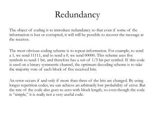
Cont’ • For combinational circuits, an undetectable fault is corresponding to a redundant wire • Redundancy can cause • Lower fault coverage • Increase circuit size • Increase dynamic power consumption • Increase propagation delay 4
Cont’ • Parallel patterns single fault propagation (PPSFP) 5
Problem Formulation • Given a circuit, we try to determine a good strategy for our PPSFP + Critical path tracing-based redundancy identifier to filter redundant wires in a reasonable condition • See if the performance can be improved by replacing SIS’s random simulation with our method 6
Summary of SIS ATPG • SIS: A System for Sequential Circuit Synthesis • Function • atpg, red_removal, short_tests • In atpg(automatic test pattern generation), first, sis uses PPSFP-based random simulation to produce the test patterns for easy-to-detect faults, then the remaining hard-to-detect faults are sent to SAT solver 7
Cont’ • Random simulation strategy • Checkpoints • Parallel patterns(32 bits) • Cover at least 10 faults every iteration(one chance), or quit 8
Fault Collapse • Fault equivalence • AND gate • All stuck-at-0 faults are equivalent • OR gate • All stuck-at-1 faults are equivalent • Inverter • Input stuck-at-0(1) is equivalent to output stuck-at-1(0) fault A C B 9
Cont’ • Fault dominance • Fault dominance relation • (C s-a-1 > A s-a-1) && (C s-a-1 > B s-a-1) • Fault can be ignored • (C s-a-1) A C B 10
Cont’ • Checkpoints theorem • Checkpoints = primary inputs + fanout branches • Sweep the circuit from PO to PI to examine every gate and replace gate’s output fault with its input fault until a PI or fanout branch is met 11
Idea • As a redundant identifier, it filters the redundant wires the more the better, but its execution time cannot excess the ATPG-based method • Our method is better than PPSFP, so if we use our method with a good strategy in SIS, it may be more efficient 12
Experimental Result(1) • Chance: 1, iteration:10, frame size:210~213 13
Cont’ 14
Experimental Result(2) • Chance: 1, iteration: 1~10, frame size: 25 15
Cont’ 16
Conclusion • The SIS can be improved by our method with a good strategy • According to experimental results, we find that testability dominates the strategy of our method • High testability->high effort in random simulation • Low testability->high effort in SAT solver 17
Future work • Check if the comparison is fair • Think over a good strategy 18