Download

1 / 20
200 likes | 363 Views
2007-2008 RIT MAV System Review (P08121). Sponsored By:. Dr. Jeffrey Kozak – Faculty Guide Michael Reeder – Team Leader Kevin Hand – Lead Engineer Todd Fernandez – ME Susan Bieck – ME Jeremy Teets – ME Cody Rorick – ME Adam Bosen – CE. …where the sky is only the beginning…

E N D
2007-2008 RIT MAV System Review (P08121) Sponsored By: Dr. Jeffrey Kozak – Faculty Guide Michael Reeder – Team Leader Kevin Hand – Lead Engineer Todd Fernandez – ME Susan Bieck – ME Jeremy Teets – ME Cody Rorick – ME Adam Bosen – CE …where the sky is only the beginning… …and the ground is likely the end…
Re-Introduction of Team Members Sue Bieck Mike Reeder Kevin Hand Jeremy Teets Todd Fernandez Cody Rorick Adam Bosen
Project Description/Customer Needs • Primary Objective: • Create a Micro Aerial Vehicle, expandable in nature for future RIT research • Simple, robust and stable in design • Capable of reading back information regarding the vehicle’s speed, angle of attack, pitch, yaw and roll rates • Flight Dynamics competition (held internationally) establishes target specifications (engineering metrics) • Max linear dimension is 80 cm • Max weight is 1 kg • Required flight time is 4 minutes • Secondary Objective: • Compete in international Flight Dynamics competition
Objective of 2007-2008 RIT MAV • Platform design decided upon • Engineering metrics/product specifications completed • List of components and materials compiled • 3-D CAD model of plane created (XFOIL, Pro-E, etc.) • Foam model built based on concept generations • Experiments designed to test components’ proper functionality • Components ordered/in team’s possession • Components in possession are in test process • Foam plane is built and glide tested
Selected Concept – Airfoil • Selig S1210 airfoil chosen for: • Weight range (500-1000g) • Efficiency at various AOA’s • Speed range (15mph+)
Selected Concept – Propulsion System • Esskay 400XT • 1.5 oz brushless motor • Allows for several prop sizes to achieve various speeds • Thunder Power TP9103 • 3 cell configuration • 910 mAh **Several props will be bought and tested to determine optimal speed of the MAV**
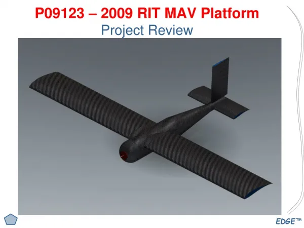
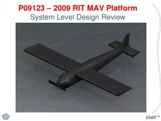
Selected Concept – MAV Design • MAV design based on: • Brainstorming sessions • Feasibility analyses • Flight dynamics calculations (reference) • Chosen design utilizes • Stream-lined cylindrical fuselage • Fuselage designed to incorporate airfoil into body • Symmetrical rear airfoil
Selected Concept – Flight Dynamics • Flight dynamics calculations led to a series of calculations to determine stability of aircraft • Calculations also aided in determining proper rear tail dimensions • Horizontal tail span – 10 in • Vertical tail span – 5 in • Horizontal & vertical tail chord – 4 in • Moment arm of the tail – 17 in
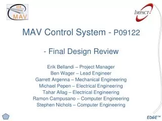
Selected Concept - Controls • Main component to be used is O-Navi microcontroller • Contains angular accelerometer, GPS, among others • Use of microcontroller will enable complex information to be sent to and received from MAV • Paparazzi considered for software architecture • Pressure transducers (velocity, AOA) • Servos (flight control)
Selected Concept – Design of Experiments • Differential pressure sensor used in conjunction with a pitot tube to determine aircraft velocity • One differential pressure sensor on each wing to determine pressure difference which will yield AOA experimentally • Angular/Linear accelerometers used to determine pitch, roll and yaw of aircraft during flight • LabVIEW, LabVIEW, LabVIEW!!!
Selected Concept – User Interface • Utilize LabVIEW to create interface: • Altitude • Velocity • Pitch • Roll • Yaw • Example shown
Tentative Bill of Materials (BOM) • Tentative BOM is shown to the right • Impact Technologies has generously donated $1,500.00 to the MAV Senior Design effort for 2008.
Completed Objectives – MSD I • Platform design decided upon – COMPLETED • Engineering metrics/product specifications completed – COMPLETED • List of components and materials compiled – COMPLETED • 3-D CAD model of plane created (XFOIL, Pro-E, etc.) – COMPLETED • Foam model built based on concept generations – COMPLETED (1st run model) • Experiments designed to test components’ proper functionality – WIP • Components ordered/in team’s possession – WIP • Components in possession are in test process – WIP • Foam plane is built and glide tested – WIP (airfoil creation)
Tentative Schedule for MSD II • Completion of blank plane (red) • Component testing (yellow) • System integration of components (orange) • Integration of system into ground model (green) • Flight tests (light blue and blue) • Base station data retrieval (purple) • MAV system integration (light green) • Completed project flight testing (gray)