Download
1 / 19
210 likes | 559 Views
The Giant Magellan Telescope Phasing System. Brian McLeod Harvard-Smithsonian Center for Astrophysics. The GMT Phasing Team. Systems Engineering Antonin Bouchez - GMTO Integrated Optics Phasing Sensor (IOPS) Francis Bennet - Australian National University Phasing Camera

E N D
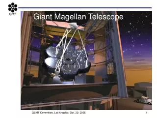
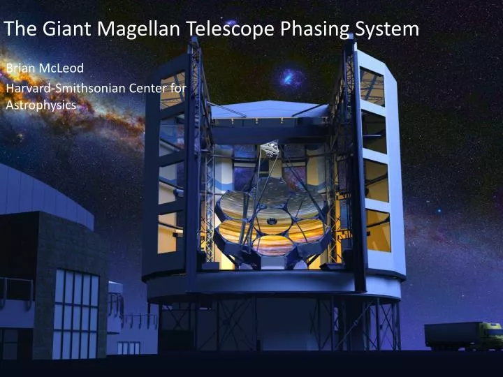
The Giant Magellan Telescope Phasing System Brian McLeod Harvard-Smithsonian Center for Astrophysics
The GMT Phasing Team Systems Engineering Antonin Bouchez - GMTO Integrated Optics Phasing Sensor (IOPS) Francis Bennet - Australian National University Phasing Camera Brian McLeod - Harvard-Smithsonian CfA Pyramid WFS Simone Esposito, Enrico Pinna – INAF OsservatorioAstrofisico di Arcetri M1 Edge sensors D. Scott Acton - Ball Aerospace M2 Edge sensors Roberto Biasi, Mauro Manetti - Microgate
Telescope Observing Modes • Natural Seeing • No phasing necessary • Ground Layer AO • No phasing necessary • Natural Guidestar AO • Correct telescope segment piston error • Correct atmospheric segment piston error (~120 nm RMS) • Laser Tomography AO • Only faint, off-axis natural guidestars available • Therefore, can correct only telescope segment piston error
Phasing Strategy: LTAO Mode 3-stage approach to phase the telescope to <65 nm RMS in the LTAO observing mode: • Initial phasing using off-axis Phasing Camera • Maintain alignment over short timescales using M1 & M2 edge sensors • Update edge sensor setpoints using the phasing channel of the On-Instrument Wavefront Sensor.
Outline • The phasing challenge • The toolbox • Metrology • Optical Sensors • Compensators • Putting it together into a system AO4ELT3 - 30 May 2013
GMT Phasing - Challenges • Ohara E6 has non-zero CTE (2.8 × 10⁻⁶ /°C) • M1 segment separations are large (30-36 cm) AO4ELT3 - 30 May 2013
Challenges: Field dependent piston • Dual segmentation leads to potential for field-dependent segment piston: • Sensitivity: 1μradM2 segment tilt compensated by M1 segment tilt leads to 10 nm of segment piston 1’ off-axis. • Performance limited by stability of M2 edge sensor system and ability to make piston measurement close to field center • Expected uncertainty in current design: 30nm at 10’
Metrology: M2 Capacitive Edge Sensors Expected piston sensitivity: 20nm RMS Considering alternative layout with additional single-axis sensors (green) to improve tilt sensitivity (Microgate Corp.)
Metrology: M1 distance interferometers Expected short-term piston sensitivity: 13nm RMS Renishaw distance- measuring interferometers
Optical Sensors: Phasing Camera Patrol radius = 6’-10’
Optical sensors: Phasing camera: Basics Reimage pupil onto masked lenslet array. Form pupil image on MEMSarray Dichroic IR Vis EMCCD Shack-Hartmann loop Grism array Dispersed fringes
Optical sensors: Phasing camera: Prototype Deployed at Magellan July 2012
Optical Sensors: Phasing camera: performance • For R<15, K<12, median seeing, 60 sec, get RMS<~50 nm with 85% sky coverage at SGP. • Fringe capture rangeis +/- 50 μm nm RMS WFE K R
Optical sensors: Integrated Optic Piston Sensor Poster 13236: Integrated Optic Segment Piston Sensor for the GMT, F. Bennet et al.
IOPS waveguide schematic Optical Sensors: Integrated Optics Piston Sensor Opto-mechanical design
LTAO Phasing Strategy Summarized 3-stage approach to phase the telescope to <65 nm RMS in the LTAO observing mode: • Initial phasing using off-axis Phasing Camera • Maintain alignment over short timescales using M1 & M2 edge sensors • Update edge sensor setpoints using the phasing channel of the On-Instrument Wavefront Sensor. OR Update edge sensor setpoints using Phasing Camera if no star for IOPS
Phasing System Summary • M1 and M2 edge sensor metrology – startup and for high-speed relative measurement • Phasing camera 6-10’ off axis – fringe capture and initial setup • NGSAO – Dual wavelength pyramid sensor measures telescope+atmosphere • LTAO – Integrated Optics Piston Sensor @ 1’ or Phasing Camera @6-10’ (no measurement of atmospheric piston)