Download
1 / 19
200 likes | 384 Views
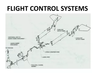
Institute of Flight Systems. Recent Activities 102 ACGSC Committee Meeting 17 October 2008, Niagara Falls, New York Oliver Brieger, German Aerospace Center (DLR) oliver.brieger@dlr.de. DLR is Germany’s aerospace research center and space agency.

E N D
Institute of Flight Systems Recent Activities102 ACGSC Committee Meeting17 October 2008, Niagara Falls, New YorkOliver Brieger, German Aerospace Center (DLR)oliver.brieger@dlr.de
DLR is Germany’s aerospace research center • and space agency Member of Hermann von Helmholtz-Association of National Research Centers (HGF)
DLR • performs basic research • develops novel technologies • builds and operates large-scale test facilities • assumes management tasks • trains junior scientists
Sites 31 research institutes and scientific/technical facilities at 8 sites 4 branches German-Dutch Wind Tunnels (DNW) European Transonic Wind Tunnel (ETW) German Armed Forces Flight Test Center Manching
Flight Sciences Cognectics Guidance & Control Flight Mechanics & Flight Dynamics, SysID and Modelling Dynamic Interaction between Human Operator and Machine Control Technology and Application, Advanced Autonomy Institute of Flight Systems Systems & Flight Safety System Integration of S.-Critical Systems, Systems Engineering Technology Validation by Experiment DLR Report DLR Report Theory Ground Experiment Flight Test & Research
Flying Testbeds Bo-105 ARTIS-Family (Micro,Midi, Maxi) VFW 614 ATTAS EC 135 - FHS USTOL / MIL Demo ?(in acquisition) A 320 Advanced Technology Research Aircraft - ATRA Full access to experimental systems and equipment -> in house design
Aircraft Wake Vortex & Atmospheric Turbulences: Modelling, Interaction and Control • Theory • Messurement • Modelling • Solutions • Verification • Application
A400M Low Level Flight Functions with ATTAS Inflight Simuation and Demonstration of Advanced Low Level Flight Functions for Large Transport Aircraft
Active Control Technology – Improved Mission Effectiveness (ACT-IME) with EC 135 FHS • Successful Demonstration of new EC-F functions • New active Sidestick concept
WASLA-HALE – Remote Mission Steering and Integration of UAV into Air Traffic Management Relais A/C AFCS /ATHR FMS MMS-Bord RAPIN+ COM 2 COM 1 Command Data Link with Intercom COM 3 GCS Braunschweig GCS Manching
Rotorcraft - New Technologies • Only 25% of noise • Only 10% of vibration level, reducing scheduled maintenance cost > 50% • Marginal Improvement of Efficiency Active Twist Blade on Test Rig Innovative New Rotor but: „Circle-shaped Rotor-Wing“ limits economy of fast flight
Flight Test Group Manching Involved in all aspects of military flight testing (mainly HQ, CFH and performance) • For Eurofighter/ Typhoon • soon for A400M
y x Eurofighter Air-to-Surface HQ Evaluation for Swing-Role Adaptation (Ground Attack Test Equipment II - GRATE II) • Based on GRATE and ATLAS systems developed in the late 80s to evaluate handling qualities during air-to-surface tracking • Array of lighted targets are placed at predefined positions on the ground • During a prolonged gun attack, target lights are illuminated in a predefined sequence • Pilot has to acquire and track the respective target expeditiously and precisely, being forced to react continuously using a high gain piloting technique • Employed to assess and optimize tracking filter with respect to gross acquisition and fine tracking Target Area Aircraft
Employment of GRATE II for Pilot Model IdentificationOptimization of Target Array Geometry • Requirement: nearly uniform and small angle variations (0.4 - 1 deg) due to small perturbations approach x x1 1 deg limit 133 m Aperture Angle [deg] x2 y 123 m y1 y2 y4 y5 Last angle alteration x3=y3 112 m 0.4 deg limit x4 102 m Distance x to reference target x5 4 x 21.5 m
3 Multi-step Approximation v a4 x 1 2 a3 a1+a2 r ( t ) a2 a1 1 a2 v v x 3 x 3 0 v v Amplitude [deg] x 4 Aperture angle progression [deg] x 4 - 1 v a3 x 5 - 2 a1 a2 a3 a4 a3+a4 - 3 - 5000 - 4000 - 3000 - 2000 - 1000 Distance x to the reference target [m] Distance x to the reference target [m] Input Signal into the Pilot-Aircraft System Defined by: • The varying line of sight between the aircraft and the individual targets • Target illumination sequence x x1x2x3 x4x5
Amplitude Spectrum Dt = 2.25s – 3s maximum of C zero location CP0.5 P0.5 Amplitude [deg] Frequency w [rad/s] - w D 1 cos( t ) D 2 t w D 2 ( t ) C0.5 t [ s ] D w [rad/s] 0 p/2 p 3p/2 2p Frequency w [rad/s] 0 p/2 p 3p/2 2p Sequence Selection • Maximized power spectra over a wide frequency range → Fourier Analysis