Download
1 / 39
390 likes | 620 Views
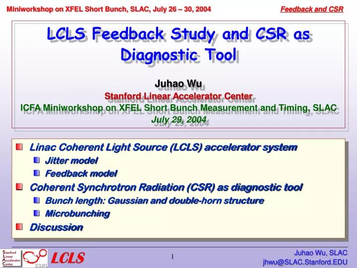
LCLS Feedback Study and CSR as Diagnostic Tool Juhao Wu Stanford Linear Accelerator Center ICFA Miniworkshop on XFEL Short Bunch Measurement and Timing, SLAC July 29, 2004. Linac Coherent Light Source (LCLS) accelerator system Jitter model Feedback model

E N D
LCLS Feedback Study and CSR as Diagnostic Tool Juhao WuStanford Linear Accelerator CenterICFA Miniworkshop on XFEL Short Bunch Measurement and Timing, SLACJuly 29, 2004 • Linac Coherent Light Source (LCLS) accelerator system • Jitter model • Feedback model • Coherent Synchrotron Radiation (CSR) as diagnostic tool • Bunch length: Gaussian and double-horn structure • Microbunching • Discussion Juhao Wu, SLAC
LCLS Accelerator System • Electron beam at birth: peak current ~ 100 ampere • XFEL calls for very high peak current ~ several kilo ampere • Compress the bunch, and accelerate the bunch Bunch Compressor; Linac Accelerator Juhao Wu, SLAC
X- X-band Jitter budget (< 1 minute time-scale) measured RF performance klystron phase rms 0.07° (20 sec) klystron ampl. rms 0.06% (60 sec) • We need a feedback system Courtesy of P. Emma Juhao Wu, SLAC
LCLS Accelerator System • LCLS accelerator system model (P. Emma): a 5-stage linac-bend segments Juhao Wu, SLAC
LCLS Accelerator System • Linac • RF • Wakefield (structure wake) • Bend (2rd order map) Juhao Wu, SLAC
LCLS Feedback System Schematic Courtesy of P. Krejcik • Observables: • Energy: E0 (at DL1), E1 (at BC1), E2 (at BC2), E3 (at DL2) • Bunch length Peak current: I1 (at BC1), I2 (at BC2) • Controllables: • Voltage: V0 (in L0), V1 (in L1), V2 (effectively, in L2) • Phase: 1 (in L1), 2 (in L2 ), 3 (in L3) Juhao Wu, SLAC
LCLS Feedback Algorithm We arelinear Juhao Wu, SLAC
LCLS Feedback System • LCLS feedback model • Include Proportional gain, Integral gain, and Derivative gain (PID): Integral gain helps at the low frequency regime • Cascade scheme: we need to keep the off-diagonal elements in the M-matrix • Pulse rep rate: 120 Hz Juhao Wu, SLAC
Bode Plot (E/E) Integral Gain helps! P:0.2 P:0.2; I:0.5 I:0.5 Juhao Wu, SLAC
Bode Plot (I/I) Integral Gain helps! P:0.2 P:0.2; I:0.5 I:0.5 Juhao Wu, SLAC
LCLS Accelerator System Jitter Measurement Peaks around 0.08 and 1.7 Hz Courtesy of P. Emma Juhao Wu, SLAC
LCLS Accelerator System Jitter Model • We model the jitter as the follows: Juhao Wu, SLAC
LCLS Feedback Performance feedback off feedback on (Integral gain:0.5) Juhao Wu, SLAC
Coherent Synchrotron Radiation • CSR as nondestructive diagnostic tool • For a group of Ne electrons • CSR spectrum • Form factor Juhao Wu, SLAC
ss 1 mm 500 m V(s)/MV/nC/m 250 m 100 m 50 m 25 m s/DsFW Linac Wake/Impedance • Linac wake Green function (K. Bane) SLAC S-Band: s0 1.32 mm a 11.6 mm s < ~6 mm • To first order in 1/k (capacitive) Juhao Wu, SLAC
Wake for parabolic distribution • For a parabolic distribution, the induced wake is Juhao Wu, SLAC
Wake-induced Cubic term • Longitudinal phase-space before BC2 Blue: only L2 Black: L2 + L1 (with BC1) Red: L2 + L1+ wake (with parabolic dist.) Wake with parabolic dist. leads to the double-horn Juhao Wu, SLAC
Wake-induced Cubic term • Longitudinal phase-space change due to BC2 Blue: after BC2 Red: before BC2 Wake with parabolic dist. leads to the double-horn Juhao Wu, SLAC
Current profile after BC2 • Wake-induced double-horn structure Black: with Laser-Heater ( ) Red: without Laser-Heater ( ) Laser-Heater smears out the double-horn, however … Juhao Wu, SLAC
Bunch spectrum after BC2 Black: with Laser-Heater ( ) Red: without Laser-Heater ( ) Blue: Gaussian with same ( ) Green: Step with same ( ) • Sharp-edge induces high freq. component Juhao Wu, SLAC
CSR spectrum after BC2 • ISR power spectrum from a bending magnet • for an azimuthal milliradian of the electron orbit () and integrated over all the vertical angles • Assuming |F|2=1%, /=1%, for 1 nC charge bunch Juhao Wu, SLAC
CSR spectrum after BC2 Black: with Laser-Heater ( ) Red: without Laser-Heater ( ) Blue: Gaussian with same ( ) Green: Step with same ( ) • Fix detector Juhao Wu, SLAC
CSR spectrum after BC2 Black: with Laser-Heater ( ) Red: without Laser-Heater ( ) Blue: Gaussian with same ( ) Green: Step with same ( ) • Fix detector Juhao Wu, SLAC
R56 l bi Z(k) DE bf >> bi or G= bf/ bi >> 1 Instability mechanism • Initial density modulation due to drive uv laser ripple energy modulation through long. impedance Z(k), • Energy modulation density modulation by a chicane • Growth of slice energy spread / emittance! Energy l t Current modulation Gain=10 10% 1% t Juhao Wu, SLAC
Microbunching after BC2 • Current profile with microbunching at 100/40 m Black: with microbunching(20% at 100/40 m) Red: without microbunching Juhao Wu, SLAC
Bunch spectrum after BC2 • Microbunching inf. in the bunch spectrum Black: with microbunching (20% at 100/40 m) Red: without microbunching Blue: Gaussian with same ( ) Green: Step with same ( ) Juhao Wu, SLAC
CSR spectrum after BC2 • Fix detector Black: with microbunching (20% at 100/40 m) Red: without microbunching Blue: Gaussian with same ( ) Green: Step with same ( ) Juhao Wu, SLAC
CSR spectrum after BC2 • Fix detector Black: with microbunching (20% at 100/40 m) Red: without microbunching Blue: Gaussian with same ( ) Green: Step with same ( ) Juhao Wu, SLAC
Microbunching after BC2 • Current profile with microbunching at 500/40 m Black: with microbunching(20% at 500/40 m) Red: without microbunching Juhao Wu, SLAC
Bunch spectrum after BC2 • Microbunching inf. in the bunch spectrum Black: with microbunching (20% at 500/40 m) Red: without microbunching Blue: Gaussian with same ( ) Green: Step with same ( ) Juhao Wu, SLAC
CSR spectrum after BC2 • Fix detector Black: with microbunching (20% at 500/40 m) Red: without microbunching Blue: Gaussian with same ( ) Green: Step with same ( ) Juhao Wu, SLAC
CSR spectrum after BC2 • Fix detector Black: with microbunching (20% at 500/40 m) Red: without microbunching Blue: Gaussian with same ( ) Green: Step with same ( ) Juhao Wu, SLAC
Microbunching after BC1 • Current profile with microbunching at 500/4 m Black: with microbunching(5% at 500/4 m) Red: without microbunching Juhao Wu, SLAC
Bunch spectrum after BC1 • Smooth parabolic distribution Black: with microbunching (5% at 500/4 m) Red: without microbunching Blue: Gaussian with same ( ) Juhao Wu, SLAC
CSR spectrum after BC1 • Fix detector Black: with microbunching (5% at 500/4 m) Red: without microbunching Blue: Gaussian with same ( ) Juhao Wu, SLAC
CSR spectrum after BC1 • Fix detector Black: with microbunching (5% at 500/4 m) Red: without microbunching Blue: Gaussian with same ( ) Juhao Wu, SLAC
Discussion • Given the jitter budge and the experiment measurement, a Feedback system is mandatory!!! • So far, studied the energy and bunch length feedback • Low frequency jitter is not hard to correct • However, the white noise is hard to deal with; need sort out what is the real white noise content • P. Emma’s ``too’’ new discovery about the timing jitter 1-to-1 transfer necessaries one more timing feedback • CSR: a good candidate for the bunch length measurement; needed for the feedback; however • The double-horn structure complicates situation • Micorbunching easier to be detected at BC1, because • The double-horn structure complicates situation Juhao Wu, SLAC
To-do list Implement the CSR-based bunch length diagnostic into the feedback simulation code Implement the timing feedback Sort out the real white noise component Create a more realistic jitter model Need to weight gain differently for different loop Juhao Wu, SLAC
Acknowledgement Collaboration with P. Emma, L. Hendrickson, Z. Huang, P. Krejcik, et al. Thank committee for the workshop and invitation Juhao Wu, SLAC