Download
1 / 20
210 likes | 333 Views
Learn about CEBO DRILL-GROUT products and CEBO Conduct-Gel solutions for optimal heat transfer and protection against ground settling and corrosion in HDD applications. Discover the benefits, applications, and requirements for successful grouting operations.

E N D
Grouting 2019 Basic Drilling Fluids HDD Applications Cebo Holland B.V.
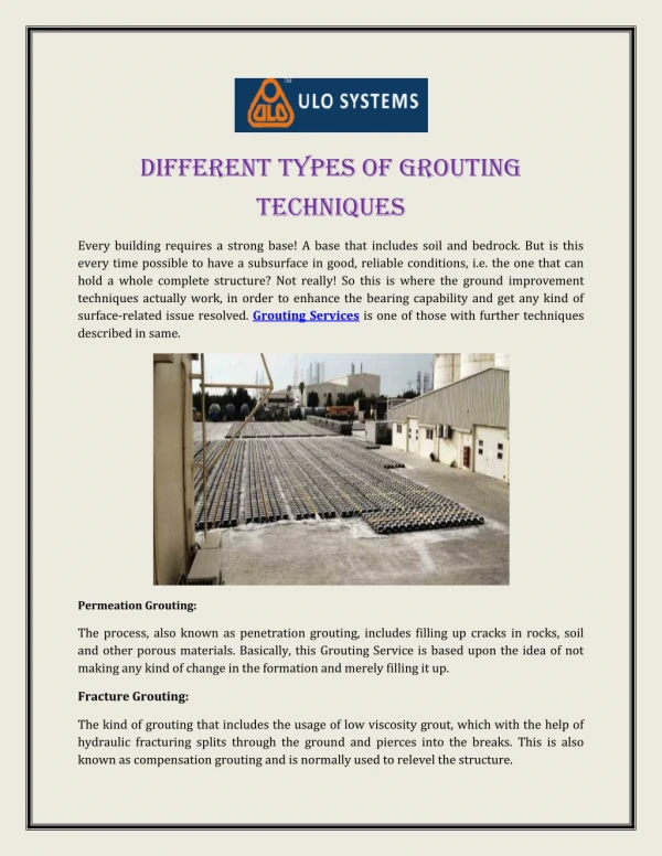
Grouting • Why Grout? • To minimize the chance of ground settling after installation of the pipe(s) • To prevent seepage of surface water into a groundwater layer • To protect steel pipes against corrosion • To gain a specific thermal conductivity and/or resistivity
Grouting • Settlement of ground after installation of the product pipe(s)
Grouting CEBO DRILL-GROUT CEBO DRILL-GROUT PLUS
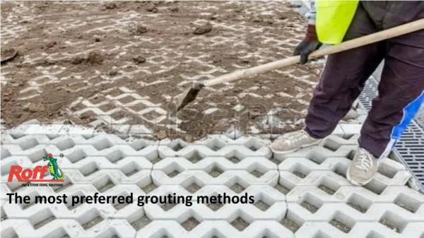
Grouting • Installation of grout using an injection pipe Injection pipe Injection pipe Grout Product pipe Ground Ground Old drilling fluid
Grouting Ground Annular space completely filled 20% 80% Barrel Reamer Product Pipe Swivel Ground
Grouting • Thermal conductive grout • To improve the transmission of heat from power cables to the ground • More efficiency from power cables • Applied between the power cable and the PE pipe • Commonly used in vertical geothermal applications • To improve the transmission of ground heat to the system
Grouting • Annulargabbetween jacket tubeandcablebackfilledwith; • Air • Water • Bentonite slurry • Building material
Grouting • Cebo Conduct-Gel • Easy mixable • Low mixing ratio • High flowability • Low weight suspension • Higher heat transfer than basic fluids • Non-hardening suspension • Removable after time
Grouting Cebo conduct-gel 1,0 Cebo conduct-gel 1,3 Cebo conduct-gel 1,5 Cebo conduct-gel 2,0
Grouting • Heat emissionfrom power line toannulargaband jacket tube • Depending on backfillingmaterial,heat transfer couldbehindered • Aim; • Optimal heat dissipationtopreventtemperaturepeaks; • Unexpected load limitations • Materialfatiques of thecables • Total cable breakdown Temperaturegradient High voltage power line Soil Jacket tube
Grouting Jacket tube, backfilledwith 2,0 W/m*K material Jacket tube, no backfilling
Grouting Profile1: constant load = 300 A Cable: 90◦C max. operationtemperature Cable load, Jacket tube not / backfilledwith 2,0 W/m*K Jacket tube notbackfilled Jacket tube backfilledwith 2,0 W/m*K
Grouting Profile 2: Standard load profile, degree of burden = 0,7 Cable: 90◦C max. operationtemperature Temperature of jacket tube notbackfilled Temperature of jacket tube with 2,0 W/m*K Load jacket tubewith 2,0 W/m*K 350 A: Load jacket tube notbackfilled
Grouting Profile 3: Load profile with feed-in of photovoltaics, Degree of burden = 0,4 Cable: 90◦C max. operationtemperature Temp. of jacket tube notbackfilled Temp. of jacket tube with 2,0 W/m*K 515 A:Jacket tubewith 2,0 W/m*K 350 A:Jacket tube notbackfilled
Grouting *Effect of drying out of thesoil was excluded
Grouting • Summary of the test runs; • Cable – jacket tube system, notbackfilled • High thermalresisitivitybetween power line and jacket tube andsurroundingsoil • Poor heat dissipation • Cable heating • Limitation of electric load (in test runs max. 350A) • Cable – jacket tube system, backfilledwith 2,0 W/m*K • Significantlyhigher heat dissipation • Lowercabletemperature • Higherelectric load (in test runs >500 A)
Grouting • Requirements; • Complete backfilling of theannulargabbetween power line and jacket tube • High flowability, especiallyfor long cable runs, (HDD > 1.000 m) • Long-term stability, otherwisevoidswith high thermalresistivitycouldarise • Easy todismantle • Highestpossible heat conductivity, adaptedtothe system performances of theentirecable run • Properties; • Easy flowing, no grains/aggregates • Easy flowing, sufficientworkability • No segregation, gel-like structure • Gel-like structure • Heat conductivityadjustiblewithina range of 1,0 – 2,0 W/m*K