Download
1 / 14
140 likes | 168 Views
Learn about gate layout design, standard cell methodology, placing NMOS at the bottom and PMOS at the top, stick diagrams, wiring tracks, well spacing, and area estimation in VLSI design.

E N D
VLSI DesignLecture 4-b: Layout Extraction Mohammad Arjomand CE Department Sharif Univ. of Tech.
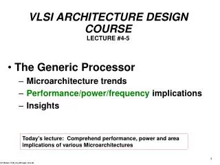
Gate Layout • Layout can be very time consuming • Design gates to fit together nicely • Build a library of standard cells • Must follow a technology rule • Standard cell design methodology • VDD and GND should abut (standard height) • Adjacent gates should satisfy design rules • nMOS at bottom and pMOS at top • All gates include well and substrate contacts
Example: NAND3 • Horizontal N-diffusion and p-diffusion strips • Vertical polysilicon gates • Metal1 VDD rail at top • Metal1 GND rail at bottom • 32 by 40
Stick Diagrams • Stick diagrams help plan layout quickly • Need not be to scale • Draw with color pencils or dry-erase markers
VDD Vin Vout GND Stick Diagrams • Stick diagrams help plan layout quickly • Need not be to scale • Draw with color pencils or dry-erase markers
Wiring Tracks • A wiring track is the space required for a wire • 4 width, 4 spacing from neighbor = 8 pitch • Transistors also consume one wiring track
Well spacing • Wells must surround transistors by 6 • Implies 12 between opposite transistor flavors • Leaves room for one wire track
Area Estimation • Estimate area by counting wiring tracks • Multiply by 8 to express in
Example: O3AI • Sketch a stick diagram for O3AI and estimate area
Example: O3AI • Sketch a stick diagram for O3AI and estimate area
Example: O3AI • Sketch a stick diagram for O3AI and estimate area