Download
1 / 33
330 likes | 479 Views
MICE running. Preamble ISIS running Step I Step(s) IV Step V (and VI). new results from T2K (13 June) and MINOS (24 June) on e appearance indications that sin 2 2 13 is >0. old fit. 90% C.L. 0. 0.04 0.08 0.12 0.16 0.20 sin 2 2 13. T2K. MINOS. note:

E N D
MICE running Preamble ISIS running Step I Step(s) IV Step V (and VI)
new results from T2K (13 June) and MINOS (24 June) on e appearance indications that sin2213 is >0 old fit 90% C.L. 0. 0.04 0.08 0.12 0.16 0.20 sin2 213 T2K MINOS note: different CP axes!
Needs confirmation but this is exciting for neutrino long baseline physics! • Large values of sin2213 would give a chance for superbeams to • have a shot at CP violation, • but Neutrino Factory remains most precise and only device able • to test oscillations very precisely • -- precision measurements of angles and mass differences, • -- tau appearance and unitarity tests • -- detailed study of matter effects • -- etc… • Physics is moving forward, no time to waste, Ionization cooling must be demonstrated
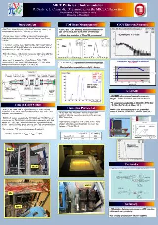
10% cooling of 200 MeV/c muons requires ~ 20 MV of RF single particle measurements => measurement precision can be as good as D ( e out/e in ) = 10-3 never done before either… Coupling Coils 1&2 Spectrometer solenoid 1 Matching coils 1&2 Matching coils 1&2 Spectrometer solenoid 2 Focus coils 1 Focus coils 2 Focus coils 3 m Beam PID TOF 0 Cherenkov TOF 1 RF cavities 1 RF cavities 2 Downstream particle ID: TOF 2 KL, EMR VariableDiffuser Liquid Hydrogen absorbers 1,2,3 Incoming muon beam Trackers 1 & 2 measurement of emittance in and out
Quantities to be measured in a cooling experiment Measurements of TRANSMISSION EMITTANCE REDUCTION EQUILIBRIUM EMITTANCE for the standard Study II optics are the main deliverables cooling effect at nominal input emittance ~10% beam line can deliver 3,,6,,10 mm (see Mark’s talk) other values can be reached by offline culling or reweighting equilibrium emittance = 2.5 mm curves for 23 MV, 3 full absorbers, particles on crest
MICE Steps m STEP I -- complete -- EMR comm. STEP II -- skip -- STEP III/III.1 -- skip -- STEP IV October 2012- March 2013 STEP V aim: April 2014 STEP VI
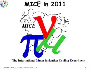
MICE Target -- Linear motor dips target at 80g -- in beam since Sept’09 571k dips -- reproducibility excellent -- tested regularly for reproducibility to test possible degradation. -- not-so-easy to build a second one that works that well!
T2.X = linear motor 2, target mech. X motor 2 presumed inferior to motor 1 nevertheless almost there! Building two new linear motors with improved tolerances. Aim at having T3 and T4 targets to install in ISIS & Spare by end 2011
MICE STEP I Superb data taking end 2009 and summer 2010! GOALS ACHIEVED See presentation by M. Rayner at FAC in Jan 2011 Rates limited by beam loss induced in ISIS.
muon rates -- required muon rate is ~50/200 per pulse without (stepI-IV)/with (StepV-VI) RF -- limitation is irradiation in ISIS due to beam losses induced by MICE target measured in Volts on Beam Line Monitors -- observed rates in MICE 2010 (6mm beam) 5 TOF1/ms/V_BLM for -beam, 30 TOF1/ms/V_BLM for +beam following a series of dedicated irradiation runs and measurements of activation ISIS allowed us to run routinely at 2V and even tried up to 10V. We are within range for STEPS I-IV further studies on how to get more muons per losses are ongoing (beam bump, timing, faster dip, etc..)
High beam loss (up to 10 V) tests (14 Aug.) • https://micewww.pp.rl.ac.uk/elog/MICE+Log/1449 • https://micewww.pp.rl.ac.uk/elog/MICE+Log/1447
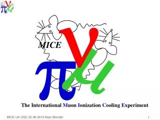
0.40 m 0.42 m Tof-0 10 x 4cm scintillator bars sx = 1.15 cm st = 50 ps 7 x 6cm bars sx = 1.73 cm st = 50 ps Tof-1 How MICE Measures e in Step 1 (t1,x1,y1) (t0,x0,y0) TOF0 TOF1 Use TOF0 and TOF1 to determine phase space parameters of the muon beam • Momentum-dependent • matrix relates • (t0,x0,y0,t1,x1,y1) • (t1,p,x1,x’1,y1,y’1) solved by iteration
e Measurement Result: Data vs MC Reconstructed transverse phase space of the baseline MICE beam (6-200) at TOF1 y (mm) vs x (mm) x (mrad) vs x (mm) y (mrad) vs y (mm) Data MC M.Rayner OxfordU
STATISTICS See John Cobb MICE note 268: Statistical error on relative change of emittance is 1% with 105 muons Presently allowed running with beam loss of 2-3 V (assume 50 + /Spill) for STEP IV: 1 measurement = 2 103 spills ~ 2 hours. (full matrix in 3 days) for step V and VI need 12 times more statistics (match RF phase!) 1 measurement = 2 104 spills ~ 20 hours. We would aim at higher rates for step V, rate is sufficient for step IV
ISIS running periods, MOM Rota and MICE runs in 2011 First semester Second semester
EMR installed in MICE hall First 3 modules, running cosmics now. Start run on 30 June. Full detector to run in Feb 2012
ISIS running Typical year consists of 5 ISIS ‘user runs’ of ~35 days each + run-ups, MP. 5 periods April 2013 to April 2014 priority to Step V installation Some additional step IV running not ruled out but lower priority Next Long Shut Down envisaged: Aug. 2014 to February 2015 new target, full EMR no running Step IV Installation Step IV: empty/LH2/(LHe) no absorber flat LiH LiH wedge + reserve
MICE Steps m STEP I STEP II STEP III/III.1 STEP IV STEP V STEP VI
Skipping steps The point was raised (Cobb) that 1.. The optics of step III is not easy to match for conservation of emittance 2. The logistics of changing from Step III to step IV is not trivial. 3. we can execute the physics program of step III and step III.1 with the magnetic channel of step IV effect on Schedule is a balance = time gained by suppressing specific installation of step II and step III time lost by required push-pull operations in replacing solid absorbers >4 mo --vs-- 3 to 6 x 8 days = Winner!
Amplitude Cooling... in empty channel Step 3 empty Step 4 empty Amp OUT Amp OUT 140 120 100 80 60 40 20 140 120 100 80 60 40 20 0 20 40 60 80 100 120 140 0 20 40 60 80 100 120 140 Amp IN Amp IN 6mm beam, SigPz = 1 MeV/c, 100k muons (T.Carlisle)
Clearly the optics of step III leads to ‘heating’ up to 5% (mis-beaviour of dispersive beam?) Step IV is much cleaner from this point of view (~0.2%)
Step IV Time to install Step IV – 168 days (about six months) Step IV running time – ~10 days Time to substitute solid absorber in FC – 8 days Hayler, Nichols • Important assumptions at this stage: • AFC module is ready and tested • LH2 infrastructure in MICE Hall is ready 23
STEP IV configurations in out STEP IV • 1.liquid H2 absorber, empty • commission system, tracker, detectors, optics • compare in /out • for various values of momentum, emittance and beta function • systematic errors • 2.liquid H2 absorber, full • measure cooling properties of liquid Hydrogen • At that point will have measured ionization cooling! • can also measure LHe (lower priority)
in out STEP IV STEP IV configurations 3.Vacuum (only He and window for trackers) execute STEP III program; compare in /out information on systematic error of final experiment information on effect of windows by comparison with
in out STEP IV STEP IV configurations 4.Solid absorbers execute STEP III.1 program; compare trackin /trackout compare in /out for various values of momentum, emittance and beta function information on emittance generating properties of materials
The MICE Energy Absorber • New Hanger Arrangement • 3 SS straps • 1 Machined SS clamp • 45 cm, t= 65 mm • Y12 is producing the LiH • Produced by Hot Isostatic Pressing (150 oC, 30,000 psi) • Final parts will be • Tested for Chemical composition and purity • Radio-graphed to ensure no voids • Machined to size • Dimensional inspection • Coated with epoxy completely 27
Will study wedge absorbers (change 6D emittance) Absorber measurements thickness 10 MeV energy loss will measure: Liq H2 330 mm LiH 65 mm Also possible (used in NuFACT beams) Liq He 410 mm Be 34 mm Al 23 mm with low priority: Plastic 50 mm Fe 9 mm Cu 8 mm
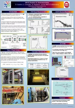
Step V STEP V “sustainable” cooling: cooling happens in the absorbers but production of cool beam requires acceleration with RF cavities old simulation (at 88MHz) Eout-Ein -1- running with shutters to commission RF cavities (no beam needed) -1’- running with LH2 and RF first with no beam to check RF noise -2- running with beam with no RF and no LH2 to check optics -3- running with beam with LH2 no RF-4- running with beam with LH2 and RF -5- or running 2-3-4- with solid absorbers? RF phase limited in optics and performance step VI!
FINAL COMMENTS Steady progress towards demonstration of Ionization Cooling Already demonstrated validity of beam line principle and emittance measurements with particle detectors On daily basis: LHe test of LH2 system, 1MW in RF unit, EMR prototype, SS repair plan, etc… Progress on global MICE Project management (Thanks Andy!) On solid ground for running step IV in Oct. 2012, aiming to start step V in 2014 before long shutdown (tough but everyone on board!) Looking forward to significant cooling measurement results!
Figure 2 A representative compilation of sensitivities of some future long baseline projects. Here the fraction of dCPwhere CP violation can be observed at 3 standard deviations is plotted as a function of q13. T2KK: T2K 1.66 MW beam to 270 kton fid volume Water Cherenkov detectors in Japan (295km) and in Korea (1050 km); DUSEL: a WBB from Fermilab to a 300 kton WC in Dusel(1300km); SPL 4 GeV, EU-BB and BB+SPL: CERN to Fréjus (130km)project; NF bl is the Neutrino Factory baseline (4000km and 7000km baselines) and NFPy+INO represents the concrete baseline from CERN to Pyhasalmi mine in Finland (2285km) and to INO in India (7152 km); PS2-Slanic is a preliminary superbeam study at1500km based on an upgrade of PS2 to 1.66MW and a 100kton Liquid Argon TPC CERN – SPC panel report , SPC meeting, 16.03.2010
From IDS-NF Intermediate Design Report IDR
Major challenges tackled by R&D expts High-power target . 4MW . good transmission MERIT experiment (CERN) Fast muon cooling MICE experiment (RAL) Fast, large aperture accelerator (FFAG) EMMA (Daresbury)