Download
1 / 9
100 likes | 228 Views
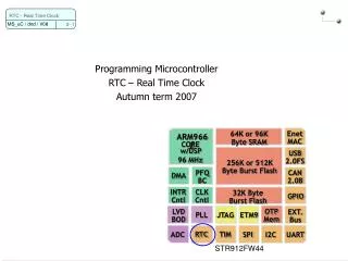
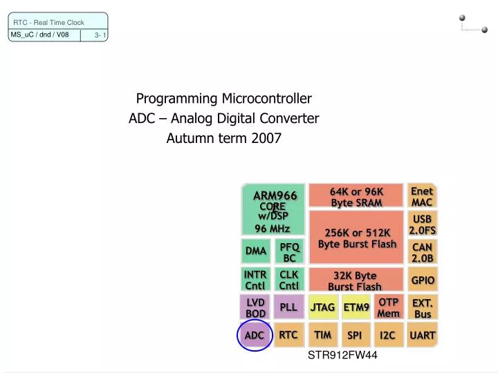
Programming Microcontroller ADC – Analog Digital Converter Autumn term 2007. 64K or 96K Byte SRAM. Enet MAC. ARM966E. CORE. w/DSP. USB 2.0FS. 96 MHz. 256K or 512K Byte Burst Flash. PFQ BC. CAN 2.0B. DMA. INTR Cntl. CLK Cntl. 32K Byte Burst Flash. GPIO. OTP Mem.

E N D
Programming Microcontroller ADC – Analog Digital Converter Autumn term 2007 64K or 96K Byte SRAM Enet MAC ARM966E CORE w/DSP USB 2.0FS 96 MHz 256K or 512K Byte Burst Flash PFQ BC CAN 2.0B DMA INTR Cntl CLK Cntl 32K Byte Burst Flash GPIO OTP Mem LVD BOD EXT. Bus JTAG ETM9 PLL RTC TIM ADC SPI I2C UART RTC - Real Time Clock STR912FW44
ADC clock: PCLK with a 8-bit frequency prescaler Resolution: 10 bits 8 input channels: 0 to 3.6V input range Single Channel / Scan modes Converts one or all 8 channels successively One-Shot or Continuous conversion Standby mode for low power consumption Analog watchdog with interrupt generation When the converted value is above or below a programmed threshold ADC Specifics RTC - Real Time Clock
ADC Block diagram (simplified) RTC - Real Time Clock
ADC register map RTC - Real Time Clock
ADC Control Register RTC - Real Time Clock
ADC Control Register (next) RTC - Real Time Clock
ADC Channel Configuration Register RTC - Real Time Clock
ADC Data Register RTC - Real Time Clock
Initialization Control register Set the Power on Reset bit (POR) Set the End of ConVersion Interrupt enable bit (ECIE) Clear the STaRt conversion bit (STR) Channel configuration register Specify the channel, which should work in conversion mode Interrupt service routine Read the result from the data register Control register Clear STR bit Clear End of ConVersion flag (ECV) ADC Configuration RTC - Real Time Clock