Download
1 / 72
830 likes | 1.22k Views
CMOS Technology. Flow varies with process types & company N-Well CMOS Twin-Well CMOS Start with substrate selection Type: n or p Doping level, → resistivity Orientation, 100, or 101, etc Other parameters. A Twin-Well Process Flow. Initial cleaning Growth of SiO 2 layer

E N D
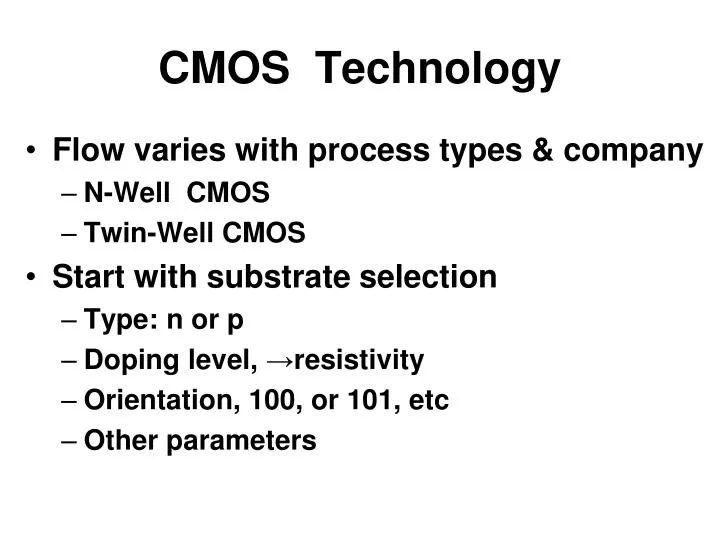
CMOS Technology • Flow varies with process types & company • N-Well CMOS • Twin-Well CMOS • Start with substrate selection • Type: n or p • Doping level, →resistivity • Orientation, 100, or 101, etc • Other parameters
A Twin-Well Process Flow • Initial cleaning • Growth of SiO2 layer • Deposition of Si3N4 layer • Spun photoresist layer
Apply mask 1 Photo process Dry etch of unprotected area
Strip photoresist Grow field oxide
Etch out Si3N4, spin photoresist Apply mask 2, photo process, etch Boron implant, form P well for NMOS
Etch out photoresist, spin new layer Apply mask 3, photo process, etch N-type implant, form N well for PMOS
Etch out photoresist High temp drive-in to complete wells
Spin photoresist, apply mask 4 Photo process, etch Boron implant to adjust N-channel VT
Spin new photoresist, apply mask 5 Photo process, etch Arsenic implant to adjust P-channel VT
Remove photoresist, and thin oxide Grow gate oxide with precise thickness
Deposit polysilicon layer Phosphorous implant to heavily dope the poly
Spin photoresist Apply mask 6, photo process Plasma etch to remove poly
Remove old and spin new photoresist Apply mask 7, photo process N- -type implant
Remove old and spin new photoresist Apply mask 8, photo process P- -type implant
Remove photoresist Deposit a conformal layer of SiO2
Anisotropically etch SiO2 layer Form sidewall spacers by poly
Grow thin “screen” oxide Spin photo resist, apply mask 9 Arsenic implant to form drain, source
Photoresist, mask 10 Boron implant (P+) for PMOS’ S & D
High-temp drive-in to activate implanted dopants and diffuse junction to their final depth
Unmasked etch to remove oxide from drain, source, and gate tops
Titanium reacts in N2 ambient Form TiSi2 when in contact with Si Elsewhere form TiN
Spin photoresist Mask 11 to protect local interconnects Etch remaining TiN
Remove photoresist Deposit conforming SiO2 layer
CMP (chemical-mechanical polish) Polish SiO2 and planarize wafer surface
Spin photoresist Mask 12 for contact holes Etch SiO2 to expose poly or TiN
Deposit a thin TiN barrier/adhesion Deposit a W layer
Deposit Al, spin photoresist Mask 13 Plasma etch
Repeat several step for metal 2 with mask 14 and 15 Passivation layer, mask 16 for bonding pads