Download
1 / 61
640 likes | 858 Views
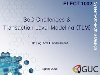
ELECT 1002. System-On-a-Chip Design. SoC Co-Design: Co-Specification Models. Dr. Eng. Amr T. Abdel-Hamid. Spring 2009. SoC HW/SW Co-Design.

E N D
ELECT 1002 System-On-a-Chip Design SoC Co-Design: Co-Specification Models Dr. Eng. Amr T. Abdel-Hamid Spring 2009
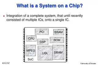
SoC HW/SW Co-Design • Co-Specification (System Model Generation): Developing system specification that describes hardware software modules and relationship between the hardware and software. • Model the (embedded) system functionality from an abstract level. • No concept of hardware or software. • Common environment: SystemC: based on C++. • Co-Synthesis: Automatic and semi Automatic design of hardware and software modules to meet the specification • Partitioning: • Dividing the functionality of an embedded system into units of computation • Scheduling: • Assign an execution start time to each task in a set, where tasks are linked by some relations
SoC HW/SW Co-Design • Allocation: • Determining on which processing elements (PEs) some computation will occur • Select the number and type of communication links and processing elements for the target system. • Assignment (Mapping): • Choosing particular component types for the allocated computation units • Co-Simulation and Co-verification • Simultaneous simulation of hardware and software
SOC Design Tasks Specificationmodel 1 PE-assembly model 2 3 5 Time-accurate Communication model Cycle-accurate Computation model 4 Implementation model 6 1. Model Generation (Co-Spec.) 2. Bus-arbitration model generation (Co-Spec.) 3. Protocol refinement (Co-Synthesis) 4. RTL synthesis (Co-Synthesis) System Design 5. IP replacement (Co-Synthesis) 6. Interconnect network generation (Co-Synthesis) Bus-arbitrationmodel 7. Co-Simulation??? Component Design
Unified HW/SW Representation • A representation of a system that can be used to describe its functionality independent of its implementation in hardware or software • Allows hardware/software partitioning to be delayed until trade-offs can be made • Typically used at a high-level in the design process • Provides a simulation environment after partitioning is done, for both hardware and software designers to use to communicate • Supports cross-fertilization (Design Modifications) between hardware and software domains
Hardware Software Model • Uses a unified representation of the system to allow early performance analysis
Unified HW/SW Representation • System Models: • State-oriented models:Finite-state machine (FSM), Petri net • Activity-oriented models:Dataflow graph, Flowchart • Structure-oriented models: Block diagram, RT netlist, Gate netlist • Data-oriented models: Entity-relationship diagram, Jackson’s diagram • Heterogeneous models: FSM/dataflow graph, State charts, *Charts. • Specification Languages: • UML • SystemC • SpecC • SystemVerilog • ESTEREL • SDL
Models and Architectures • Models are conceptual views of the system’s functionality • Architectures are abstract views of the system’s implementation • Model: a set of functional objects and rules for composing these objects • Architecture: a set of implementation components and their connections
Example: An Elevator Controller Architecture Memory I/O CLC Processor Flip-Flops I/O Ports Hardware (RTL) Description System Level (General Purpose Proc.)
System Models: • State-oriented models:Finite-state machine (FSM), Petri net, ASMs • Activity-oriented models:Dataflow graph, Flowchart • Structure-oriented models: Block diagram, RT netlist, Gate netlist • Data-oriented models: Entity-relationship diagram, Jackson’s diagram • Heterogeneous models: FSM/dataflow graph, State charts, *Charts.
Data Flow Diagram W = Z * (X+Y) • support hierarchy • suitable for specifying complex transformational systems • inherent data dependencies • do not express temporal behaviors or control sequencing • weak for modeling embedded systems
Heterogeneous: Data Control Flow Graphs • Graphs contain nodes corresponding to operations in either hardware or software • Often used in high-level hardware synthesis • Can easily model data flow, control steps, and concurrent operations because of its graphical nature. Pipeline Representation
Finite State Machines • Reactive System • continuously react to external and internal stimuli at their environment’s speed e.g. telephones, automobiles, operating system, etc. • To describe reactive behavior: states and events are good medium • Advantage • used to describe and analyze control sequences • yield better to analysis and synthesis than alternative control models due to their finite nature
State Transition Diagrams S0 • Used to visually represent an FSM • Emphasis is on identifying states and possible transitions • Circles represent States • Arrows represent Transitions Transitions 01/11 Initial State S1 Input/Output 01/01 01/10 11/10 011/00 S3 S2 1-/11 State
State tables • Table is another way to represent an FSM with an emphasis on exploring all Event/State combinations • Similar to the truth table • Doesn’t contain the system clock when specifying its transitions (it is implicit that transitions occur only when allowed by clock) • Unless different stated, all the transitions are occurring on the positive edge of the clock
FSM Example • General Machine Description: • deliver package of gum after 15 cents deposited • single coin slot for dimes, nickels • no change
Vending Machine Example D D Reset 0¢ N 5¢ N 10¢ N, D 15¢ [open]
Mealy FSM The FSM where the outputs are used immediately
Moore FSM Each bit of the output is passed through a memory element.
Mealy FSM • Output is dependent on the inputs and the current state transition condition 1 /output 1 state 2 state 1 transition condition 2 /output 2
Moore FSM • Output is dependent only on the current state transition condition 1 state 2 / output 2 state 1 / output 1 transition condition 2
Moore vs. Mealy FSM • Moore and Mealy FSMs can be functionally equivalent • Equivalent Mealy FSM can be derived from Moore FSM and vice versa • Mealy FSM Has Richer Description and usually requires smaller number of states • Smaller circuit area • Mealy FSM computes Outputs as soon as Inputs change • Mealy FSM responds one clock cycle sooner than equivalent Moore FSM • Moore FSM has no combinational path between Inputs and Outputs • Moore FSM is more likely to have a shorter critical path
Mealy FSM - Example • Mealy FSM that Recognizes Sequence “10” 0 / 0 1 / 0 1 / 0 S0 S1 0 / 1 Meaning of states: • S0: No elements of the sequence observed • S1: “1” observed
Moore FSM - Example • Moore FSM that Recognizes Sequence “10” 0 1 0 S0 / 0 1 S1 / 0 S2 / 1 1 reset 0 Meaning of states: • S0: No elements of the sequence observed • S1: “1” observed • S2: “0” observed
Finite State Machines • Disadvantage • Flat fashion, lots of states result in unstructured, unrealistic, and chaotic state diagram (State Space Explosion) • Not suitable for describing concurrent system • Solution: • Abstract State Machines (ASMs) • Hierarchical Concurrent Finite State Machine (HCFSM or State Charts) • Hierarchical Finite State Machines with Multiple Concurrency Models (*Charts)
Quake Example • Types of behavior to capture: • Wander randomly if don’t see or hear an enemy • When see enemy -> attack • When hear an enemy -> search and chase • When die -> Spawn • If health is low and see an enemy ->retreat • Extensions: • When see power-ups during wandering -> collect them • Exactly borrowed from John Laird and Mike van Lent’s GDC tutorial
Example FSM Attack E,~D ~E E D E Wander ~E,~S,~D S Chase S,~E,~D E ~S D ~E S D • States: • E: enemy in sight • S: sound audible • D: dead • Events: • E: see an enemy • S: hear a sound • D: die • Action performed: • On each transition • On each update in some states (e.g. attack) Spawn D
Example FSM Problem Attack E,~D ~E E D E Wander ~E,~S,~D S Chase S,~E,~D E ~S D ~E S D • States: • E: enemy in sight • S: sound audible • D: dead • Events: • E: see an enemy • S: hear a sound • D: die Spawn D Problem: Can’t go directly from attack to chase. Why not?
Better Example FSM ~S Attack-S E,S,~D Attack E,~S,~D ~E S D D ~E E E Wander ~E,~S,~D S Chase S,~E,~D E ~S D ~E S D • States: • E: enemy in sight • S: sound audible • D: dead • Events: • E: see an enemy • S: hear a sound • D: die • Extra state to recall whether or not heard a sound while attacking Spawn D
Example FSM with Retreat Attack-ES E,-D,S,-L Retreat-S -E,-D,S,L Attack-E E,-D,-S,-L S • States: • E: enemy in sight • S: sound audible • D: dead • L: Low health • Worst case: Each extra state variable can add 2n extra states • n = number of existing states L -S L -L E -E E -L Retreat-ES E,-D,S,L Wander-L -E,-D,-S,L E -L E L -S -L L S Retreat-E E,-D,-S,L Wander -E,-D,-S,-L -E -E E D D Chase -E,-D,S,-L D D Spawn D (-E,-S,-L) S
Hierarchical FSMs • What if there is no simple action for a state? • Expand a state into its own FSM, which explains what to do if in that state • Some events move you around the same level in the hierarchy, some move you up a level • When entering a state, have to choose a state for it’s child in the hierarchy • Set a default, and always go to that • Or, random choice • Depends on the nature of the behavior
Hierarchical FSM Example • Note: This is not a complete FSM • All links between top level states still exist • Need more states for wander Attack Wander ~E E Chase Pick-up Powerup ~S S Spawn Start Turn Right D ~E Go-through Door
HCFSM (StateCharts) • Extension of conventional FSMs by David Harel: (1987) • Hierarchy • Concurrency • Communication • StateCharts • Highly structured and economical description language • Compact • Expressive • Compositional • Modular
StateCharts • Classical automata not useful for complex systems (complex graphs cannot be understood by humans). • Introduction of hierarchy StateCharts [Harel, 1987] • StateChart = the only unused combination of “flow“ or “state“ with “diagram“ or “chart“
Introducing hierarchy FSM will be in exactly one of the substates of S if S is active(either in A or in B or ..)
StateCharts: Hierarchy • When a superstate is active, exactly one of its substates is active
Definitions • Current states of FSMs are also called active states. • States which are not composed of other states are called basic states. • States containing other states are called super-states. • For each basic state s, the super-states containing s are called ancestor states. • Super-states S are called OR-super-states, if exactly one of the sub-states of S is active whenever S is active. superstate ancestor state of E substates
OR States • An OR-state can contain other states as its internal substates (hierarchical internal structure); • super OR-state is active, if and only if one of its immediate substates is active (exclusive or); • When the control enters a (super) OR-state, its default substate is entered and becomes active; • When the control leaves a (super) OR-state, all its substates become inactive!
Default state mechanism • Try to hide internal structure from outside world! • Default state • Filled circleindicates sub-state entered whenever super-state is entered. • Not a state by itself!
Combining history and default state mechanism same meaning
History mechanism • For input m, S enters the state it was in before S was left (can be A, B, C, D, or E). If S is entered for the very first time, the default mechanism applies. • History and default mechanisms can be used hierarchically. (behavior different from last slide) k m
StateCharts: Concurrency • And Decomposition: Orthogonal product of A and D A = {B, C} D = {E, F, G} Y = A X D
Concurrency • Convenient ways of describing concurrency are required. • AND-super-states: FSM is in all (immediate) sub-states of a super-state; Example:
Entering and leaving AND-super-states • Line-monitoring and key-monitoring are entered and left, when service switch is operated. incl.
Timers • Since time needs to be modeled in embedded systems, • timers need to be modeled. • In StateCharts, special edges can be used for timeouts. If event a does not happen while the system is in the left state for 20 ms, a timeout will take place.
Broadcast mechanism • Values of variables are visible to all parts of the StateChart model. • New values become effective in phase 3 of the current step and are obtained by all parts of the model in the following step. StateCharts implicitly assumes a broadcast mechanism for variables. StateCharts is appropriate for local control systems (), but not for distributed applications for which updating variables might take some time ().
StarCharts (*charts) • Limitation on concurrency of HCFSM • StateCharts loosely defines state transitions in concurrent FSM’s to be simultaneous • Broadcast mechanism • Undetermined behavior on circular dependencies • *Charts are models of computation supporting concurrency better • Loosely synchronized concurrency model • Dataflow • Tightly synchronized concurrency model • Discrete Event • Synchronous/Reactive (SR)