Download
1 / 36
390 likes | 660 Views
Receiver Systems. Suzy Jackson – based on previous talks by Alex Dunning & Graeme Carrad. The Basic Structure of a typical Radio Telescope. Ours look like this. MRO PAF . ATCA 3/7/12mm. Parkes 10/50cm. The Receiver. On the outside. Vacuum Dewar. Feed Horns. The Receiver.

E N D
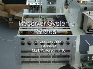
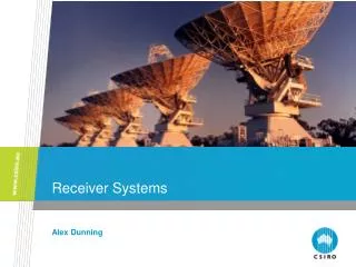
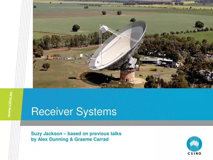
Receiver Systems Suzy Jackson – based on previous talks by Alex Dunning & Graeme Carrad
The Basic Structure of a typical Radio Telescope CSIRO. Receiver Systems for Radio Astronomy
Ours look like this... MRO PAF ATCA 3/7/12mm Parkes 10/50cm CSIRO. Receiver Systems for Radio Astronomy
The Receiver On the outside... Vacuum Dewar Feed Horns CSIRO. Receiver Systems for Radio Astronomy
The Receiver On the inside... Ortho-Mode Transducers Amplifiers CSIRO. Receiver Systems for Radio Astronomy
system temperature minimum detectable flux Integration Time Effective Collecting Area Observing Bandwidth CSIRO. Wide Band Receiver Upgrade of the CASS Compact Array
The Australia Telescope Receivers Current upgrade C/X W K Q L/S 2.5cm-7cm 12mm-18.7mm 10cm-25cm 4.6cm-6.7cm 6mm-10mm O2 absorption 2.8mm-3.5mm 3.2cm-3.7cm CSIRO. Receiver Systems for Radio Astronomy
Parkes Receiver Bands CSIRO. Receiver Systems for Radio Astronomy
Receiving the signal – Feed horns Feed Signal Captures the focused microwaves into a waveguide output Waveguide output CSIRO. Receiver Systems for Radio Astronomy
Feed Horns • Designed to match the focal ratio of the antenna • Matches the waveguide impedance to free-air impedance • Design compromises: • Size & weight • Spillover/efficiency • Bandwidth • Loss CSIRO. Receiver Systems for Radio Astronomy
Coupling noise into the System Feed Coupler Signal Noise source 7mm waveguide coupler Noise coupled in through small holes Noise coupled in through vane 21cm waveguide coupler 12mm noise source CSIRO. Receiver Systems for Radio Astronomy
Separating Polarisations – Ortho-mode Transducers (OMTs) 3mm Ortho-mode transducer Pol A Polariser Feed Coupler Signal Noise source Pol B Separates incoming signal into two linear or circular polarisations Linear OMTs exhibit higher polarisation purity over broad frequency bands (usually) 12mm Ortho-mode transducer 4cm Ortho-mode transducer CSIRO. Receiver Systems for Radio Astronomy
Low Noise Amplifiers (LNA) Pol A Polariser Feed LNA Coupler Signal To conversion System Noise source Pol B LNA High Electron Mobility Transistor (HEMT) CSIRO. Receiver Systems for Radio Astronomy
Why is the first Low Noise Amplifier so important? T1 T2 T3 Feed Signal Second Stage Amplifier Third Stage Amplifier LNA
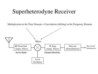
The Conversion System Level Adjustment Frequency Conversion Filter Amplifier Signal To Digitiser • Contains: • more amplification • band defining filters • frequency conversion • level adjustment • signal detection • band shaping CSIRO. Receiver Systems for Radio Astronomy
Filters High Pass Filter Low Pass Filter Band Pass Filter 21cm band filter CSIRO. Receiver Systems for Radio Astronomy
Mixing it down – Frequency Conversion Mixer (Multiplier) Signal 1 Signal 1 × Signal 2 Signal 2 cos(ω1t)cos(ω2t)=½[cos((ω1+ω2)t)+ cos((ω1-ω2)t)] Power Power Frequency Frequency Δf Δf CSIRO. Receiver Systems for Radio Astronomy
Mixing it down – Frequency Conversion Mixer (Multiplier) Signal 1 Low pass filter Signal 2 cos(ω1t)cos(ω2t)=½[cos((ω1+ω2)t)+ cos((ω1-ω2)t)] Power Power Frequency Frequency Δf Δf CSIRO. Receiver Systems for Radio Astronomy
Mixing it down – Frequency Conversion Mixer (Multiplier) Signal 1 Local Oscillator cos(ω1t)cos(ωLOt) → ½cos[(ω1-ωLO)t] Power Power flo Upper Side Band (USB) Frequency Frequency Δf Δf CSIRO. Receiver Systems for Radio Astronomy
Mixing it down – Frequency Conversion Mixer (Multiplier) Signal 1 Local Oscillator cos(ω1t)cos(ωLOt) → ½cos[(ωLO-ω1)t] Power Power flo Lower Side Band (LSB) Frequency Frequency Δf Δf CSIRO. Receiver Systems for Radio Astronomy
Mixing it down – Frequency Conversion Mixer (Multiplier) Signal 1 Local Oscillator Band pass filter Power Power flo Frequency Frequency Δf Δf CSIRO. Receiver Systems for Radio Astronomy
Single Sideband Mixers cos[(ω1- ωLO)t] (USB) cos[(ωLO- ω1)t] (LSB) 2cos(ω1t) 0 (USB) √2cos[(ω1- ωLO)t] (LSB) 2√2cos(ω1t) RF Signal -cos[(ω1- ωLO)t] (USB) cos[(ωLO- ω1)t] (LSB) 2sin(ω1t) sin[(ω1- ωLO)t] (USB) -sin[(ωLO- ω1)t] (LSB) CSIRO. Receiver Systems for Radio Astronomy
Single Sideband Mixers √2cos[(ωLO- ω1)t](USB) 0 (LSB) 2√2cos(ω1t) RF Signal Upper sideband Local Oscillator Signal Lower sideband CSIRO. Receiver Systems for Radio Astronomy
I/Q Mixers 2cos(ω1t) cos[(ω1- ωLO)t] +cos[(ω1+ωLO)t] cos[(ω1- ωLO)t] 2√2cos(ω1t) I/Q Baseband Signal RF Signal -sin[(ω1- ωLO)t] 2cos(ω1t) sin[(ω1+ ωLO)t] -sin[(ω1-ωLO)t] CSIRO. Receiver Systems for Radio Astronomy
Or Graphically I/Q Baseband Signal RF Signal Power Power flo Frequency Frequency Δf Δf CSIRO. Receiver Systems for Radio Astronomy
Attenuators – The Volume Knob • Allow the signal level to be varied • May be several in the system • Usually set automatically Just like some other systems if you turn the signal down too far all you get is noise and if you turn it up to far you get distortion! CSIRO. Receiver Systems for Radio Astronomy
Of course real systems are a little more complicated. They often contain multiple conversions and many amplification and filter stages.... But that’s the gist of it. CSIRO. Receiver Systems for Radio Astronomy
What is the rest of the stuff? What’s this? What’s this? CSIRO. Receiver Systems for Radio Astronomy
Electronics CSIRO. Receiver Systems for Radio Astronomy Supplies and monitors all amplifier voltages and currents Monitors system temperatures and pressures
Cryogenics 15K section 80K section Helium Compressor Cold finger Refrigerator in the Parkes 12mm receiver Helium Lines Helium Refrigerator CSIRO. Receiver Systems for Radio Astronomy
Gap Thermal Isolation waveguide 15K section Vacuum Dewar Low Noise Amplifiers Helium Refrigerator cold finger Copper Radiation Shield 80K CSIRO. Receiver Systems for Radio Astronomy
….but why do we need to cool our receivers at all? CSIRO. Receiver Systems for Radio Astronomy
How weak is the signal? Effective area of Parkes telescope dish 10Jy radio source → 10 × 10-26 W m-2Hz-1 × 1900m2 × 1 × 109 Hz = 2× 10-13 W Bandwidth of Digital Filter Bank 3 Boltzmann's constant Your hand → 1.38× 10⁻²³ W Hz-1K-1 × 300K × 1 × 109 Hz = 4 × 10-12 W Mobile Phone → ≈ 1W Lunar Distance Mobile Phone on the moon→ ≈ 1W ÷ 4π (3.8×10⁸m)2 ÷ 5×10⁶Hz ≈ 10Jy 3G transmit bandwidth CSIRO. Receiver Systems for Radio Astronomy
Like your hand all the components in the receiver system contribute a thermal noise signal which masks the astronomical signal we are trying to observe. By cooling the receiver we reduce these thermal sources of noise and improve the sensitivity of the receiver by 7-10 times. CSIRO. Receiver Systems for Radio Astronomy
Reduce noise by cooling visible output amplify Electronic device generates a signal audio output Cold stuff (liquid nitrogen) – good for making ice cream. CSIRO. Receiver Systems for Radio Astronomy
Contact Us Phone: 1300 363 400 or +61 3 9545 2176 Email: enquiries@csiro.au Web: www.csiro.au Thank you CSIRO Astronomy and Space Science Suzy Jackson RF Engineer Phone: 02 9372 4359 Email: Suzy.Jackson@csiro.au Web: www.csiro.au/org/CASS