Download
1 / 55
570 likes | 676 Views
Preliminary Design Review October 16, 2012. Smart ENergy Delivery ( SEND). Christopher Corey, Josh Crowley, John Fischer, Tim Myers, Neil Severson, Kristine Thompson. SEND Mission. Design and implement smart microgrid energy delivery system

E N D
Preliminary Design Review October 16, 2012 Smart ENergy Delivery (SEND) Christopher Corey, Josh Crowley, John Fischer, Tim Myers, Neil Severson, Kristine Thompson
SEND Mission • Design and implement smart microgrid energy delivery system • Combine multiple/varied energy sources in most efficient use of resources possible • Utilize advantages and address drawbacks of each source
SEND Mission • Intelligently match energy collection to load requirement • Design system to be as grid-independent as possible
Team Motivations • Develop innovative system that has ability to combine sources and pursues intelligent management of sources and loads • Team is varied in skill sets and fields of interests • Reflected in requirements and functional roles of project
Project Motivation • Rwandan Orphans Project Catch-Up School • Kigali, Rwanda • Provide education for 200-300 orphans and local community children • Unreliable grid • Primary Goals • Cheap operation • Robust • Simple
Microgrid Background • Rise of renewable energy sources has increased the popularity and practicality of localized, grid-independent, and highly efficient power systems • Flexible power solutions to meet needs in many settings, including developing countries
Societal Impacts • Increase the effectiveness and efficiency of small scale power systems • System concept able to supply steady power to facilities such as schools, medical facilities, and community centers in areas of expensive and/or unreliable grid connection
Basic System Goals • Convert solar and grid power to single homogeneous energy carrier (DC bus) • Store energy in battery system for use when resources are unavailable • Delivery energy to both DC and AC loads • Monitor load usage and display to user through web interface • Ability to isolate system components for protection
Reach Goals • Predictive load profiling • System mode control by the user • Optimum power point tracking for solar • Weather solar resource prediction • Add scalability • Allow for multiple source possibilities • System architecture may be followed for higher power applications • Load prioritization and control
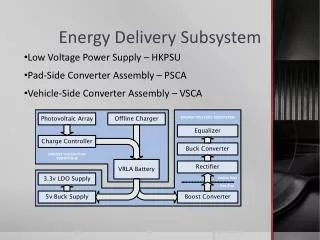
Power Inputs • Two control signals • Variable DC output to bus/battery voltage • AC constant voltage output to bus • 2 Charge Controllers • Bridge Rectifier • Charge Controller
Controller • 3 control signal outputs, one control input from Linux Server • Load data output to Linux Server • Current and voltage measurements from AC Rectifier, solar converter • State of charge and load monitoring input for decision making
Load Monitoring • Separate in-line SCRs for load control • Monitoring hardware with output to controller • Spec’d for max draw of 55W and up to 4 loads
PV Array • Monocrystalline • Most efficient • Most expensive • Polycrystalline • Less efficient than mono • Less expensive • Thin Film • Lowest efficiency and density • Least expensive • Potentially available from University
Battery • Lead-acid for best emulation of large scale implementation • AGM deep-cycle • Maximum safety • Low self-discharge • Low hydrogen emission • High charge rate • Maintenance free • Deliverable by UPS
Solar Energy Power Electronics • Responsible for drawing and converting power from the solar panel, outputting to power bus without overcharging battery Solar Converter / Charge Controller Variable DC Battery Voltage DC Power Bus Solar Panel Battery Voltage DC Battery
Solar Energy Converter • Implemented as DC-DC switching converter • Buck/boost to be determined by solar panel voltages • Output voltage is controlled by the power bus • Set by the battery voltage • This, duty cycle from controller, and converter M(D) set the PV operating point
Solar Energy Charge Controller • Prevent overcharging of battery with charge controller • Solar panel may be producing power even though battery is at max capacity • Must also prevent power from flowing back into panel during times of no insolation
Grid Energy Rectifier • Responsible for drawing energy from grid when deemed necessary, outputting to power bus without overcharging battery Battery Voltage DC 120V 60Hz AC Power Bus AC Grid Grid Rectifier Battery Voltage DC Battery
Grid Energy Rectifier • Implemented using a full-wave rectifier and switching (buck) regulator • Will receive an input from the controller dictating whether it is in operation
Grid Energy Charge Controller • The grid rectifier must also make sure to not overcharge the battery using a charge controller • Design will be similar to the solar energy charge controller
Charge Controller Implementation • System control should prevent excess power to battery, but a safety backup is needed • The two charge controllers must also make sure to not exceed the maximum charge rate of the battery with their combined output currents
Testability • Design will keep testability in mind • Allow for subcomponents to be tested on their own • Ex: Converter will be capable of being tested without solar panel input or charge controller output for proper DC-DC conversion • Verify small pieces of functionality individually
Part Tolerance • Design somewhat hinges on choice of solar panel • Operating voltage range dictates converter type • Currently some of most difficult / high risk components • Project hinges on success of this subsystem
Required functionality • Brain of operation • Central controller • Controls the inputs to provide appropriate power to the loads and battery
Inputs • Current and voltage measurements from the solar panel • Current readings from the grid connection • State of charge of the battery • User inputs • Web interface settings and readings • Load monitoring measurements
Outputs • Load control – on/off • Data to the web interface • Solar panel / converter control • Rectifier control (on/off)
Basic Functionality • Calculating available power from input sources • Power point tracking (PPT) for solar panel(s) • Calculating required power to be delivered • Controlling external hardware • AC grid connection • Solar converter / power point tracking • Includes turning off inputs with insufficient power • Reporting data to the web interface
Goal Functionality • Change of operation based on user mode • Load priority control • Use predictive models as an input for a higher efficiency system • If it is going to be sunny all day, don’t use the grid to charge the battery the night before • If the grid is unreliable on Tuesdays, charge the battery in advance • Enable optimum power point tracking when appropriate
Options for implementation • GPIC – General Purpose Inverter Controller • National Instruments power controller board • Microcontroller and custom PCB
GPIC-General • General Purpose Inverter Controller • Robust device for controlling grid tied and high power systems • Built in FPGA • Real time operating system • Power protocol support
GPIC- Advantages/Disadvantages • Advantage • Simplifies a lot of implementation • Disadvantage • No design experience with a microcontroller • Far more robust than our product needs • Unit cost would be high since the GPIC is expensive
Microcontroller - Analysis • Advantages • More design experience • Board design • High power considerations • Choosing the right microcontroller • Much more cost effective implementation • Options we don’t need can be eliminated • Disadvantages • Large added effort to the system design and implementation
Testability • Testing will be divided into each subsystem of control • Example: power point tracking can be tested by testing a closed loop converter circuit with bench top power supply
Part Tolerance • There are no required parts for initial design • After PCB fabrication, packages must remain the same for easy integration
Web Monitoring • Web interface does not require specialized software for access • Enables monitoring of load power consumption • Load Management (On / Off) • Load profiles, for automatic power management
Load Management • Solid State Relays • Non-invasive current sensing
Web Server • Beagle Bone • Arm Cortex A8 • Has a webserver pre-installed, running on the Angstrom Linux distribution. • Serial UART, I2C, SPI
Schedule • Sept 25 • Initial Requirements Specification and Use Case Models • Oct 16 • Preliminary Design Review • Present Functional Decomposition Level 0 and 1 • Oct 23 • Functional Decomposition Complete • Functional Decomposition to Level 3 • Nov 6 • Proof-of-Concept Bench Testing • Power Point Tracking- Optimum and Peak • Switching - Converter Manipulation • Apache Server for Web Interface Current Monitoring • Nov 15 • Demonstration of major hardware and software components and subsystems critical to major functions. • Web Interface • Power Point Tracking • Inverter, Converters, Rectifier • Dec 6 • Critical Design Review (CDR) • Dec 13 • Proof-of-Concept Open Lab Symposium • Jan 17 • Final Architecture and Requirements Specification Complete • Jan. 24 • Detailed Design Draft • Software Implementation design • Order PCBs / Complete BOM • Feb 7 • Bench Testing of Prototype Whole System (Hardware and Software) • Feb 21 • Complete test analysis and report results • Mar 7 • Develop initial integration test plan • Mar 14 • Final integration test plan complete • Mar 21 • Complete integration testing • Apr 11 • Final Demonstration (EXPO) Testing • Apr 25 • EXPO - Demonstration for Public. • May 2 • Complete all technical documents
Division of Labor Appendix II: Division of Labor
Safety • High currents and voltages in use throughout design • Each board will use over-current protection • System will use “breaker box” to ensure modularity, provide additional protection • Safe usage practices will protect group members