Download
1 / 46
850 likes | 2.29k Views
Microelectronics Processing Plasma Etching. Dry Etch. Chemical reaction or physical etch between gas etchants and surface material on wafer:. Dry etching methods Glow discharge methods Dry physical etching (Sputter etching) Plasma assisted etching Dry chemical etching (Plasma etching)

E N D
Microelectronics Processing Plasma Etching
Dry Etch Chemical reaction or physical etch between gas etchants and surface material on wafer: • Dry etching methods • Glow discharge methods • Dry physical etching (Sputter etching) • Plasma assisted etching • Dry chemical etching (Plasma etching) • Reactive ion etching (RIE) • Ion beam methods • Ion mlling • Reactive ion beam etching • Chemical assisted ion milling • Common materials to dry etch • Si, SiO2, Si3N4, Al, W, Ti, TiN, TiSi2, Photoresist • Difficult materials to dry etch • Fe, Ni, Co, Cu, Al2O3, LiNbO3, etc.
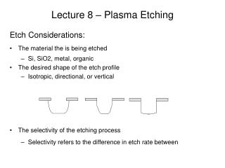
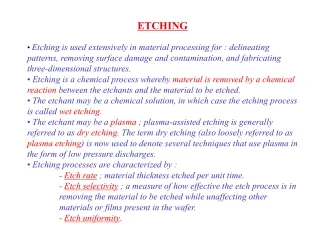
Dry Etch Process • Characteristics of Dry Etch Process • Highly selective • Anisotropic etch • For use of features smaller than 3 microns • Expensive equipment • Limited human exposure to hazardous chemicals • RF Power safety risks
Physical etch • Reactive Ion etch • Chemical (plasma) etch Dry Dry Etch Techniques
On earth we live upon an island of "ordinary" matter. The different states of matter generally found on earth are solid, liquid, and gas. We have learned to work, play, and rest using these familiar states of matter. Sir William Crookes, an English physicist, identified a fourth state of matter, now called plasma, in 1879. Plasma is by far the most common form of matter. Plasma in the stars and in the tenuous space between them makes up over 99% of the visible universe and perhaps most of that which is not visible. Natural plasma Man-made plasma Sources: http://www.plasmas.org/rot-plasmas.htm http://www.4thstate.com/publications/21stCentury.htm Plasma: the 4th state of the matter
Homogeneous and heterogeneous processes in plasma processing
Dry Etch Process • Physical Etch • Also referred to as ion beam etching, sputtering, ion .milling • Ions bombard wafer surface causing molecules to .sputter off the surface - Argon introduced into RF Power Chamber • Advantages - Low level of undercutting - Anisotropic etch • Disadvantages - Low selectivity rate - Requires high level of RF Power
Sputter etching • In this process all of the electrical energy, usually RF, is applied to the substrate. • Physically bombard the films to be etched with energized chemically inert ions or atoms. • Material is removed by ion bombardment of the substrate. This process is most often used to pre-clean substrates prior to deposition. • Glow discharge is used to energize chemically inert ions or atoms (e.g., Ar) • Highly anisotropic etching • Damage to underlying material => may change device properties • Rarely used in VLSI
Dry Etch Process Ion Beam Etcher
Dry chemical etching (Plasma etching) • Purely chemical etching. • RF energy is applied to a separate electrode with the substrates grounded. Chemical reaction between etchant gas and surface layer of wafer etches the wafer. • Glow discharge is used to produce chemically reactive species (atoms, radicals, or ions). • Advantage - High selectivity rate • Disadvantage - Isotropic etch
Plasma assisted etching • Plasma assisted etching sequence • Take a molecular gas • CF4 • Establish a glow discharge • CF4+e CF3 +F + e • Radicals react with solid films to form volatile product • Si + 4F SiF4 • Pump away volatile product (SiF4 )
RF-powered Plasma Etch System RF-powered plasma etch system Steady-state voltage distribution in RF-powered plasma etch system
Plasma Etching Mechanisms Chemical etching Due to their incomplete bonding, free radicals are highly reactive chemical species. Various reactions and species present in a plasma
Reactive Ion Etcing (RIE) • Combines both physical and chemical etching techniques • If RF energy is applied to the substrates in a low pressure halogen-rich environment, material can be removed by both chemical means and ion bombardment of the substrate surface. Greater control over line widths and edge profiles is possible with oxides, nitrides, polysilicon and aluminum. • Accomplished by replacing the neutral gas in a r.f. sputtering system by one or more chemical species • Glow discharge is used to produce chemically reactive species (atoms, radicals, or ions) and chemically inert ions • Widely used in VLSI fabrication • Advantages - High selectivity rate - Anisotropic
Chemical vs. chemical/physical etching Chemical + physical etching (using reactive neutral species and ionic species) Anisotropic etching Purely chemical etching (using only reactive neutral species) Isotropic etching
Effect of the inhibitor w/o inhibitor => Isotropic w/ inhibitor => Anisotropic fast inhibitor deposition => Bevelled walls
Importance of RIE • Importance of reactive ion etching • Highly anisotropic etching • Precise pattern transfer • High resolution • Less consumption of chemicals • Cost effective • Environmentally benign • Clean process • Vacuum • Ease of automation
Quartz tube Barrel plasma system
High density plasma (HDP) system Electron Cyclotron Resonance (ECR) Inductively coupled plasma (ICP) • ECR vs ICP • ECR was introduced at OPT in 1985. • ICP was introduced much later (1991- 1995) for plasma processing. • most important with both: independent control of ion energy and ion current density • lower (substrate) electrode grounded, RF driving opt.
How to Control Anisotropy? • Ionic bombardment damage exposed surfaces. • Sidewall coating by inhibitor prevents sidewall etching.
Example 1: How to Control Selectivity?
Example 2: Si etching in CF4 + O2 mixture. How to Control Selectivity?
In General: Etching Process Includes Several Sequential Steps Example 1: RIE of Al lines.
Example 2: Etching of deep trenches. Sequential Steps in Etching process
Sequential Steps in Etching deep trenches Solution: Multiple step RIE sequence.
Dry Etch Process Summary • Factors Influencing Dry Etch Process • Etch rate - RF Power level - Gas formula - Etch Temperature • Pressure - Extremely high pressure results in an isotropic etch - Low pressure with high energy can damage wafer
Dry Etch Process Summary • Factors Influencing Dry Etch Process • Micro-loading - Different etch rates across wafer surface - Ashing can occur • Post-etch corrosion - Due to residual etchant left on wafer after final rinse - Using a none Chlorine based etchant like Fluorine …..eliminates the problem.
PSG BPSG Plasma-Etching Gases Used in VLSI Fabrication
Wafer Cleaning • Resist Stripping • Removes residual resist after etch process • Wet stripping - For use on wafers that have not been plasma ….…..etched - For non-metallic surfaces an acid solvent is used - For metallic surfaces an organic solvent is used • Plasma Stripping - For use on wafers that have been etched by plasma - Uses oxygen as stripping plasma to remove …..photoresist