Download
1 / 23
230 likes | 389 Views
CSC Trigger Test Beam Report. Cast of many. Beam Test of 2 CSC’s at X5a. /.

E N D
CSC Trigger Test Beam Report Cast of many
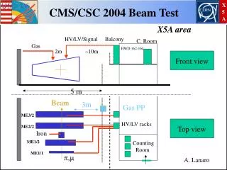
Beam Test of 2 CSC’s at X5a / Goals:1)Verify that the peripheral crate electronics (mainly DMB/TMB) are ready for production2) Complete an electronic chain test of data transmission from CSC front-end electronics to counting-room trigger electronics, all operating synchronously with the 40 MHz structured beam3) Test new XDAQ-based software
Beam Test Setup TTC crate Trigger primitives DAQ Data PC FED crate 1 DDU Track Finder Crate Peripheral Crate 2 DMB, 2 TMB 1 CCB, 1 MPC TRIDAS • 2 CSC’s, all on-chamber boards • Up to 80K events read out in 2.6s spill beam S1 S3 S2 CSC 2 CSC 1
CSC Peripheral Crate From front-end cards Clock & Control Board (CCB) with TTCRx Muon Port Card (MPC), which sends trigger primitives on optical links DDU, interface to DAQ 2 Trigger Motherboards (TMBs) for trigger primitive generation, and 2 DAQ Motherboards (DMBs) for chamber read out
CSC Track-Finder Crate MPC, for in-crate tests Sector Processor, receives optical data CCB with TTCRx
2003 Test Beam Chronology • Phase I – structured beam • May 23-June 1 • ALCT timing tests • CLCT and TMB studies • High-rate tests • Phase II – unstructured beam • June 13-28 • CLCT and TMB studies • Low-rate and high-rate tests • Phase III – additional structured beam • September 18-22 • Trigger optical link data transmission tests (MPC to SP) from peripheral electronics to counting room electronics ALCT = anode pattern logic & BX assign CLCT = cathode pattern logic
Phase I Results • Optimal timing found • Fairly high efficiency (~98-99%) achieved • Peripheral crate system basically working as desired • Chamber angle, HV, threshold scans
1.2 ms 23 ms SPS orbit period 2003 Synchronous Beam Structure 48 bunches 25 ns bunch spacing bunch width 3-5 ns Structure repeats during 2.6 s spill length
BX efficiency vs. ALCT delay setting 0-31 ns Bunch Structure, ALCT Delay Tuning • Expect muons in 48 out of 924 bx verified by CLCT BXN from data Chamber 1 Chamber 2
BX Distributions With Optimal Anode Delays • Note logarithmic scale • Cathodes: • Data mostly in 3 BX (no fine time-adjustment possible) • Anodes: • Data 98.7%in 1 BX(after fine time-adjustment) • Chamber 1 • Chamber 2
CLCT Positions • Relative position of key half-strip from CLCTs from Chamber 2 vs. Chamber 1 • Note: Chamber 1 is vertically higher than Chamber 2 (thus the offset in position). • Zoom
abs(strip3-strip8) abs(strip3-strip8) Correlated LCT Efficiency abs(wg3-wg8) The efficiency to identify a correlated LCT (ALCT+CLCT) in csc #3 in a straight line path from an LCT found in csc #8 (within a 2.5 half-strip and 2.5 WG tolerance) is: • 98.6% in one BX • 99.5% in two BX (correct BX or one after) • 99.7% in three BX (correct BX 1) (as determined from Track-Finder data from Phase 3) abs(wg3-wg8)
Chamber #1 CLCT 2,000 1,500 CLCT Rate (KHz) 1,000 data consistent with dead-time = 225 ns 500 0 0 500 1,000 1,500 2,000 2,500 3,000 Beam Intensity (KHz) Expected LCT rate at LHC < 25 KHz (ME1/1) Trigger Rate Tests SLHC (10xLHC) SLHC (10xLHC)
Test Beam, Phases 2 & 3 • Timing-in procedures improved & documented • Very high efficiencies achieved • Highest trigger efficiency of 99.9% required low rate (few kHz) • 2-chamber “excellent event” (CFEB, CLCT, ALCT) efficiency limited to 99% due to CFEB timing • Improved scans taken: • Angle scan • HV scan • Comparator threshold scan • Pattern requirements scan • Logic scope read out on most data • True time history of LCTs logged by Track-Finder • QPLL tested
CSC Track-Finder Trigger Home-built VCXO & PLL clock patch added to clean incoming TTC clock for links, but TTC QPLL also tested Test 3 × 1.6 Gb/s optical link connections from CSC electronics Uses TLK2501 chipset from TI Requires very stable reference clock for error-free operation Failed during May tests without PLL
TTC QPLL Mezzanine card • Three made available to CSC group for testing during Sept.03 structured beam test • Provides stable clock signalsat 40, 80, and 160 MHz at correct LHC frequency • Installed on Clock and Control Board (CCB) with 40 MHz clean clock sent to backplane and 80 MHz clock sent by twisted pair to SP and MPC • Noticed that CCB commands have 1 BX extra latency with TTCRq TTCRq
PLL Results • Using either the home-built VCXO+PLL solution or the CERN QPLL solution for the 80 MHz reference clock to TLK2501 receivers: • PLL locks to incoming machine clock • Measured frequency: 40.078893(1) MHz • No errors on optical links reported over many hours of PRBS and data tests • Data successfully logged by both CSC DAQ and CSC Track-Finder readout • SP data FIFO synchronized to L1A
TTCRq (QPLL) Test Results • QPLL 80 MHz clock directly to MPC transmitters & home-built VCXO+PLL for SP receivers: • No link errors for 20 minute PRBS test • QPLL 80 MHz clock directly to SP receivers andMPC uses default clock multiplier: • No link errors for 15 minute PRBS test • Successfully logged data for 10K events (run 5151) • QPLL 40 MHz clock on TF crate backplaneand SP uses DLL in FPGA for clock multiplier: • Solution tried for Phase 1 (May) structured beam running • Link errors observed in PRBS test • TTCRq on CCB in peripheral crate • Able to take data with same trigger efficiency (i.e. TTCRq works for peripheral crate electronics as well and is compatible with TTCRm)
Data-taking Mode, Phase 3 • Most data logged using two independent DAQ systems: • “CFEB Control” for DDU data (same as Phases 1&2) • “SP DAQ” for Track-Finder data (standalone SP readout) • SP records 5 BX of input data for each L1A, with most trigger data arriving on central BX • Allows study of time-dependence of trigger data • XDAQ-based event builder also able to log data • Underlying SP code the same as for standalone DAQ since it was written using XDAQ • All analysis of SP and DDU data from either DAQ system is done using the XDAQ-based software
Data Comparison CSC Data from DAQ CSC Track-Finder Data CSC 1 CSC 2
Detailed TMB–SP Comparison • Run TMB data through MPC simulation to compare with SP • MPC is not directly read out • Use BXN reported by TMB for each LCT • Preliminary comparison between SP and TMB for all 5 BX read out by SP for every L1A match: • 98% agreement for ~70K events • Mismatches between TMB and SP data are in BX assignment only, not in LCT frames
SP – TMB Mismatches • Nearly all of the mismatches involve differing BX assignment for LCTs from the TMB for csc#8 • Data frames are in agreement, however • Excluding csc#8 in these cases and comparing TMB and SP for csc#3 near perfect agreement • Just 32 discrepancies from an analysis of 60K events, where BX assignment of TMB for csc#3 differs • For these mismatches, the SP usually has the LCTs on the central BX in the SP read-out • So trigger data appears to be good! • Conclusion for DAQ readout of TMB data: • TMB #8 has BX error 2% of time • TMB #3 has BX error 5×10⁻⁴ of time • Will re-do analysis using BXN reported by ALCT