Download
1 / 48
480 likes | 598 Views
Status of the LINAC2 project. Cristina Vaccarezza on behalf of the SPARC-X team. The SPARC-X team.

E N D
Status of the LINAC2 project Cristina Vaccarezza on behalf of the SPARC-X team
The SPARC-X team D.Alesini, S.Bertolucci, M. Bellaveglia, M.E.Biagini, R.Boni, M.Boscolo, M.Castellano, A.Clozza, G.Di Pirro, A.Drago, A.Esposito, M.Ferrario, L.Ficcadenti, D. Filippetto, V.Fusco, A.Gallo, G. Gatti, A.Ghigo, S.Guiducci, M.Migliorati, A.Mostacci, L.Palumbo, L.Pellegrino, M.Preger, C.Sanelli, M.Serio, F.Sgamma, B.Spataro, A.Stella, F.Tazzioli, C.Vaccarezza, M.Vescovi, C.Vicario, INFN-Frascati F.Alessandria, A.Bacci, F.Broggi, S.Cialdi, C. DeMartinis, D. Giove, C.Maroli, M.Mauri, V.Petrillo, M.Romè, L.Serafini, INFN-Milano M.Mattioli, P. Musumeci, M. Petracca, INFN-Roma1 L.Catani, E.Chiadroni, A. Cianchi, C. Schaerf, INFN-Roma2 F.Ciocci, G.Dattoli, A.Doria, F.Flora, G.P.Gallerano, L.Giannessi, E.Giovenale, G.Messina, P.L.Ottaviani, G. Parisi, L.Picardi, M.Quattromini, A.Renieri, C. Ronsivalle, ENEA-Frascati J.B. Rosenzweig, S. Reiche, UCLA , Los Angeles, CA, USA D. Dowell, P. Krejcik, P. Emma, SLAC, Stanford, CA, USA
Outline • LINAC2 project goal • SPARXINO proposal & scientific case • General layout, Operating scenario • Preliminary cost estimate • Beam Dynamics & FEL simulation results • Summary
energy upgrade: 1.5 GeV e-- 1 GeV e+ • 2 GeV option for e- (X-band acc. sections) Project Goal • High brightness beam injector for SASE and seeded FEL experiments (SPARX project) • High Energy Beam Test Facility
Italian Initiatives a) Feb 2001: Call for proposals- 7.5 M€ for R&D SPARC (CNR-ENEA-INFN-INFM-S.Trieste-U.Roma2) b) Dec 2001: Call for proposals- 67 M€ for a X-ray FEL source 1) SPARX (CNR-ENEA-INFN-Univ.Roma2) 2) FERMI (INFM-Sincrotrone Trieste)
From the SPARX proposal: “X-rays are presently utilized in many research and application fields, for : High peak brightness and short pulse duration (few femtoseconds) will be the main characteristics of the SPARX source. By using a 2.5 GeV linear electron accelerator and two magnetic undulators it will be possible to emit radiation at 10 nm and 1.5 nm. Exploitation of 3rd and 5th harmonics will allow emission in the range between 10 and 2 nm for the first beam line and between 1.5 and 0.3 nm for the second beam line.” • Atomic, molecular and cluster physics • Plasma and warm dense matter • Condensed matter physics • Material science • Femtosecond chemistry • Life science • Single Biological molecules and clusters • Imaging/holography • Micro and nano lithography
The final decision of the Research Ministry was to support two strategic programs: FERMI A VUV-FEL user facility at 40-100 nm SPARX An R&D program for a X-ray FEL test facility at 3-10 nm
I = 2.5 kA K = 3 se = 0.03 % en=4 lcr [nm] en=1 Energy [GeV] I = 1 kA K = 3 se = 0.1 % en=4 lcr [nm] en=1 Energy [GeV] TheSPARX-ino opportunity
SPARX-ino proposal: • upgrade the DAFNE Linac to drive a 3-10 nm SASE-FEL • beam energy : 1.2 - 1.5 GeV • upgrade the injector to a RF photo-injector (SPARC-like) • Study group is preparing a proposal within 2005
Brilliance of X-ray radiation sources 12.4 1.24 0.124 l (nm) FEL Covering from the VUV to the 1 Å X-ray spectral range: new Research Frontiers SPARX
Scientificcase • “Time resolved X-ray microscopy”, D. Pelliccia, CNR-INFN • “Image reconstruction of non periodic nanostructured objects using coherent X-ray diffraction (CXD)” , G. Campi, CNR-IC • “Proprietà ottiche del “mezzo vuoto” a corte lunghezze d’onda” G.Cantatore Uni-TS • “Low energy X-rays QED tests”, M. MilottiUni-UD • and more onRadiation Transport, Diagnostics, Beam Handling, Detectors and Ultrashort Radiation Pulses FOR MORE INFO... http://www.lnf.infn.it/conference/sparx05/
F. Bonfigli et al, SPARX workshop, LNF 9-10 May 2005 …objectives: • Input from the workshop: Wavelength range as close as possible to the water window (~ 2.5 – 4.5 nm) … and to the carbon window • Flexible design: SASE & Seeded configurations • Improve coherence length • Short pulses (fs range) • Increase wavelength operation range
Schematic layout: 1.2 GeV (basic) E= .150 GeV E= .490 GeV E= 1.2 GeV SPARC f= -22° R56= 26÷32 mm DL BC L0 L1 L2 X-band X-band sz~ 210mm sz~ 50÷90 mm sd < 1 E-3
The DAFNE LINAC The main LINAC components are the following : • Thermionic gun • Prebuncher and buncher at f=2.856GHz. • High current TW LINAC with output energy 250 MeV • Positron converter • Capture section • Low current e+e- TW LINAC with output energy 510 MeV.
RF gun Linac1: Low Energy section
Etot ~ w 4 S-band : 1.5 GeVe-,1GeVe+ Now : Etot ~ 1.2 GeV Etot ~ w 3 X-band 2 GeV e- Linac2: High energy section dogleg start
Operating Scenario Sparxino @ 1.5 GeV &: • e+ 510MeV w damping (+ accumulator) • Dafne data taking • Dafne high energy w ramping • Dafne high luminosity w time sharing • e+ 1 GeV • BTF experiments • on energy in Dafne2 with new injection system
Preliminary cost estimation 1/3 SPARXino – 1.2 GeV S-Band 1 new waveguide system (M€ 0.4) 1 X-band station (M€ 1) 1 SPARC clone (M€ 5) 750 MeV 1 magnetic chicane (M€ 0.6) 480 MeV 4 new S-band stations (M€ 2.8) Estimated cost: M€ (4.8 + 15% + 5) = 10.5M€ +7M€ (buildings & plants upgrade) > 1100 MeV
Preliminary cost estimation 150 SPARXino – 1.5 GeV S-Band 2/3 1 new waveguide system (M€ 0.5) 1 X-band station (M€ 1) 1 SPARC clone (M€ 5) 750 300 1 compressore (M€ 0.6) 4 new acc. sections (M€ 0.7) Estimated cost M€ (7.0 + 15% + 5) = 13 M€ +7M€ (buildings & plants upgrade) 6 new stations (M€ 4.2)
Preliminary cost estimation SPARXino – 1.8 GeV S+X Band 3/3 750 600 480 MeV > 1800 MeV
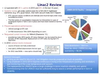
Beam Dynamics • Working point analysis • Invariant envelope matching principle • Jitter sensitivity and optimization • Microbunching instability
Beam optics dogleg to the undulator mag. compressor SPARC matching line old Linac
Parmela simulation Np=50k Two possible working points:a) Ipkav 450A w X-band at gun exit photoinjector exit Ipk-av 450A final beam Ipk-av 1.1 kA
Two possible working points:b) Ipkav 300A wo X-band at gun exit photoinjector exit Ipk-av 300A final beam Ipk-av 1.4 kA
l= 4 nm l= 5 nm l= 3 nm
High energy scenario E~1.5 GeV Sparxino0x High Energy l= 3 nm
Df= -1° Laser pulse jitter Ipk-av ~450 A reference Df= +1°
Df= -1° Laser pulse jitter Ipk-av ~450 A reference Df= +1°
Df= -1° Laser pulse jitter Ipk-av ~300 A reference Df= +1°
Df= -1° Laser pulse jitter Ipk-av ~300 A reference Df= +1°
from Elegant with Np=2M from the photoinjector exit up to undulator entrance lf =9 mm, Af= 1 % no modulation
from Elegant with Np=2M from the photoinjector exit up to undulator entrance lf =15 mm, Af= 30 % l0 =5 mm, A0= 5 %
in detail: lf =15 mm, Af= 30. % lf =9 mm, Af= 1 % lf =25 mm, Af= 11 %
about a laser heater… • to increase uncorrelated energy spread and…. • Fast (slice length determined by laser pulse length) control on the longitudinal electron phase space • Convert energy modulation into density modulation. Enhanced SASE. (Ref. Zholents Phys. Rev. ST Accel. Beams 8, 040701, 2005) • Attosecond radiation with a few optical cycle-laser slicing technique (Ref. Zholents and Fawley, PRL 92, 224801, 2004) • Short current spike at the bunch tail to study superradiance regime (Ref. Giannessi, Musumeci, Spampinati, Journal of Applied Physics, 98, 043110 (2005)) • Weak FEL detection with a modulated laser-based beam heater (Ref. Emma et al. PAC 2005)
e-beam @ the UM • Beam energy 1.2 GeV • Flat longitudinal current profile ~ 1kA • Pulse Duration ~ 300μm ~ 1 ps • Slice energy spread < 2 10-4 • Slice emittances < 1 mm-mrad
Resonance condition 1.5 GeV 1.5 kA 1.0 GeV 1.0 kA SPARC Undulator 2.8 cm period Reference: Beam Energy 1.2 GeV Peak Current 1 kA Slice energy spread < 2 10-4 Slice emittance < 1 mm-mrad Tuning range 3.5 – 15 nm Low Energy : 1.0GeV & 1.0kA High Energy : 1.5GeV & 1.5kA SPARC Undulator λUM=2.8 cm – KMAX~ 2.5 Wavelength tuning range - 15 – 4 nm
3° harmonic data SASE – PerformancesSimulations made with GENESIS 1.3 + Perseo for the high order harmonics SASE PULSE (4.5nm – 33m)
Peak brilliance [Phot./(s mrad2 mm2 0.1% bw)] 0.1% λ Spectrum SASE Spectrum @ 4.5 nm – 33m
λ~ 30 nm Ef =ηmEi~ 0.6 nJ Pf~ 3 kW cδtf~ 60 μm Ar λ~ 30 nm E ~ 0.4 μJ P ~ 8 MW δt ~ 50 fs ~ 6 μm Monochromator ηm = 0.08 x 0.5 x 0.25 x δti/δtf UM1 λu= 4.2 cm K = 3.89 5 UM 48 periods each λres ~ 30 nm Seeding to increase longitudinal coherence: HHG in Ar+Monochromator X 6 (X8) UM2 (SPARC) λu= 2.8 cm K = 1.51 6 UM 77 periods each λres ~ 5 nm (3.75 nm)
HHG in Ar + monochromator cont. 5 nm Energy per pulse ~ 100 μJ N phot. ~ 2x10¹² Coherence length ~45 μm 5 nm 3.75 nm Energy per pulse ~ 10 μJ N phot. ~ 1x10¹¹ Coherence length ~30 μm 5 nm
SUMMARY • LINAC upgrade layout proposed w a preliminary cost estimate • Photoinjector Beam Dynamics studies: • 2 stable w.p. considered • Jitter sensitivity analysis & optimization • Microbunching instability study • NEXT: • Prototypes realization • Tests at SPARC on techniques and systems for SPARXINO • Components and installation