Download
1 / 41
410 likes | 482 Views
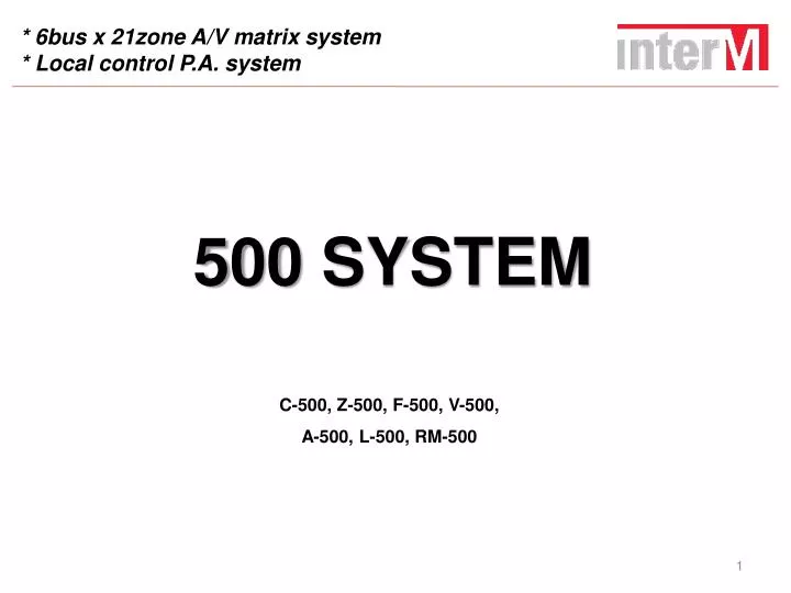
* 6bus x 21zone A/V matrix system * Local control P.A. system. 500 SYSTEM. C-500, Z-500, F-500, V-500, A-500, L-500, RM-500. Contents. 500 System 1. Sales point 2. Target market 3. Products 3-1. C-500 (Main System Controller) 3-2. Z-500 (Zone Output Selector)

E N D
* 6bus x 21zone A/V matrix system * Local control P.A. system 500 SYSTEM C-500, Z-500, F-500, V-500, A-500, L-500, RM-500
Contents 500 System 1. Sales point 2. Target market 3. Products 3-1. C-500 (Main System Controller) 3-2. Z-500 (Zone Output Selector) 3-3. V-500 (Video Matrix Selector) 3-4. F-500 (Fire Sensor Receiver) 3-5. A-500 (Modular Digital Amplifier) 3-6. L-500 (Local Controller) 3-7. RM-500 (Remote Mic. Station) 4. System configuration 5. Block diagram
1. Sales point • 6 bus multi A/V matrix systemAudio/Video : each 8 input, 6 bus, 21 zone Audio Matrix System • Zone expansion by adding Z-500 6 bus x 10 sets of Z-500 (21 zones) = 210 zones • Priority broadcasting EM > FIRE > TIMER > PAGING > RM1, 2, 3, 4 > LOCAL > BGM • Multi channels with digital amplification[ 7+1(spare) channel ] x 3 : total 21+3(spare) channel digital modular amplifier • Pre AMP : 5 channel MIC input, MIC mix On/Off selection of each bus • Extreme easiness of setting stepwise fire-alarm per each floor. • Extreme easiness of operation and installation by intutional analogue style user interface
Sales point Local control system • Local broadcasting in individual zones (by MIC. & line input of source) • Local control (bus selection & volume control) at all zones • No need of additional power supply.* Power is supplied from Z-500 through CAT5 cable. • Easy installation using CAT5 cable.
ON AIR Sales point • AUDIO and VIDEO synchronized control • Easyoperation with analogue style user interface. • Monitoring of broadcasting status of set or BGM input A/V total control system
RS-232C Sales point Network control via Ethernet line ETHERNET CLIENT SERVER PC Remote control and monitoring on the PC and network * Power on/off, volume up/down, BGM selection etc.
Incorporates with existing models • Source equipment CD-610, CD-611, CD-660, TU-610, PC-9335AD etc. • Multi-voice file, program timer PV-632, PW-642. • Telephone paging TP-631. • Speaker line checker SC-624. • PD, PB PD-9359, PD-659, PD-658, PB-607 etc.
2. Target market • Audio visual broadcasting with flexible control options required applications. • Voice evacuation system required applications. • Single and small to medium sized applications • Remote broadcasting required applications. • Local self-broadcasting of its’ own zone required applications. • Education sites : School, college, educational institute, kindergarten, training centre • Shopping facilities : Department store, retail, shopping mall • Advertising medium : Customized audio visual commercial broadcasting according to each target per zone. • Accommodation : Hotel, hospital, nursing home, resort • Public building : Office buildings, Restaurants • Religious facility : Church, mosque
3-1. C-500 [Main System Controller] • Selective 6 BUS outputs for 8 BGM channel inputs (8x6 Matrix) • Monitoring function to check signals and bus outputs coming to BGM through monitor speaker. • Various function (PP+PE+Matrix. 5 MIC mixing) • V-500 input control linked with input selection. • Remote-controlled by PC using RS-232C port and TCP/IP. • 3 chimes and 2 sirens usable during broadcasting and emergency • Priority broadcasting (EM>FIRE>TIMER>PAGING>RM1~4>LOCAL>BGM) • Free voltage (100-240V 50/60Hz)
Front panel 1. POWER BUTTON : Red-standby, Green-ON. 2. CHIME BUTTON : Selecting and operating 3 types of chimes. Convenient to use before or after broadcasting. 3. CHIME LEVEL CONTROL VOLUME 4. BGM SIGNAL DISPLAY LED (SIGNAL LED) : GREEN on input signal of BGM 1~8. 5. MIC SIGNAL DISPLAY LED (SIGNAL AND CLIP LED) : GREEN on input signal of MIC 1~5, RED for CLIP 6. MIC MIX SELECT BUTTON AND INDICATOR Select button of CHIME, SIREN, MIC inputs and Mixing for BUS 1~6 output. Red LED on MIC mixing selected. 7. BGM SELECT BUTTON : BGM 1~8 selection for BUS 1~6 output. 8. BUS CHANNEL INDICATOR : Displays selected BGM for BUS 1~6 output.
9. BUILT-IN EM MIC : Built-in condenser MIC used during fire and EM broadcasting. 10. SYSTEM OPERATION STATUS DISPLAY LED : Represents system operation and displays broadcasting status by turning on of each LED according to operation of the selected function. 11. EM MIC LEVEL CONTROL VOLUME :Output control volume of EM broadcasting. 12. EM TALK BUTTON : Press this button and talk in emergency for voice announcement to the zone indicated as EM broadcasting status at Z-500 during EM broadcasting. Talk close to built-in EM MIC with button pressed during broadcasting. 13. MONITORING SELECT INDICATOR :Displays a channel to monitor BGM input/BUS output. 14. EM ALL SELECT BUTTON :Select/release all zones connected to Z-500 system as EM broadcasting status. 15. EM TEST BUTTON :Tests the operation status of Fire Automatic Broadcasting, and can test fire contact broadcasting by selecting the desired zone irrespective of contact of F-500. 16. SYSTEM PRIORITY OPERATION STATUS INDICATOR 17. MIC INPUT LEVEL CONTROL VOLUME :Volume control of MIC 1~5 input level. 18. MIC TONE CONTROL VOLUME : Volume control of TREBLE and BASS tones for MIC 1~5 input. 19. BUS VOLUME INDICATOR . 20. BUS TONE CONTROL VOLUME : Volumecontrol of TREBLE and BASS tones for BUS 1~6 output. 21. BUS OUTPUT LEVEL CONTROL VOLUME : Volumecontrol of output level of MIC 1~6. 22. MONITORING SOURCE SELECT BUTTON 23. SIREN OPERATION BUTTON : Operating flat/wave siren. GREEN LED on selecting siren. 24. MONITORING CHANNEL SELECT BUTTON 25. SIREN SOUND CONTROL VOLUME 26. MONITORING OUTPUT SOUND CONTROL VOLUME 27. SIREN OUTPUT SELECT BUTTON 28. MONITORING SPEAKER
Rear panel 1. MIC INPUT 2. BGM INPUT 3. TIMER INPUT 4. AC POWER INPUT TERMINAL 5. MAIN POWER SWITCH 6. DC POWER INPUT TERMINAL 7. PAGING INPUT 8. VIDEO MATRIX SYSTEM (V-500) COMMUNICATION TERMINAL 9. ZONE SELECTOR (Z-500) TERMINAL 10. DRP RECORD BUTTON 11. REMOTE CONTROL COMMUNICATION TERMINAL 12. FIRE BROADCASTING SOUND SOURCE SELECT SWITCH 13. SERIAL COMMUNICATION TERMINAL 14. FIRE BROADCASTING OUTPUT VOLUME 15. REMOTE CONTACT OUTPUT TERMINAL 16. AUDIO SOUND SOURCE OUTPUT TERMINAL 17. EM MIC TERMINAL
Electrical specifications A. Electrical specifications i. INPUT SENSITIVITY MIC INPUT (BALANCED) 1~5 MIC/PHANTOM MIC…………..…………..… -50dB/600Ω LINE……………………………………….…… -10dB/20kΩ BGM INPUT (STEREO) 1~8 …………….……………………..… -10dB/20㏀ ii. OUTPUT LEVEL BALANCED OUTPUT ……………………………………….…… OdB ± 3dB iii. TOTAL HARMONIC DISTORTION MIC INPUT……………………………………………..…………… less than 0.1% BGM INPUT ………………………………………………………… less than 0.05% iv. SIGNAL TO NOISE RATIO MIC INPUT……………………………………………………..…… better than 60dB BGM INPUT…………………………………………………….…… better than 80dB B. General feature i. AUDIO INPUT BGM 1~8 STEREO INPUT MIC 1~5 BALANCED INPUT (LINE/MIC/PHANTOM MIC) INT/EXT EM MIC, TIMER, PAGING LINE INPUT Built-in IC memoryfor CHIME and Fire broadcasting ii. AUDIO OUTPUT BALANCED OUTPUT for each bus and priority broadcasting Built-in monitor speaker for monitoring BGM & BUS iii. Communication terminal RS-232 with server PC for remote-control RS-422 with Z-500 for monitoring broadcasting status and system control RS-422 with V-500 for video system control iv. Power source AC 100~240V 50/60Hz, DC 24V
3-2. Z-500 [Zone Output Selector] - 6 Bus x 21 Zone Output (6 x 21 Matrix) - Local self-broadcasting using L-500(local controller) up to 21zones. (L-500x21eas, Bus selection, Volume control, MIC andLineinput) - RM-500 connectable up to 4eas (each 21channel control) - V-500 video output controllable linked with zone selection. - Future expandability - Pre-amp output(zone 1,8,15 for High power amplifier.) - Selectable EM / Timer broadcasting zone. - Can be operated incorporated with SC-624 Line checker
Front panel 1. PAGING BROADCASTING OUTPUT DISPLAY LAMP Determine using dip switch on the rear side whether PAGING broadcasting is output. Display lamp turns on at the zone where switchis set to ON. 2. ZONE BROADCASTING STATUS INDICATOR EM/FIRE/TIMER/PAGING/RM/BUS *If all Zone’s status connected with system is ‘-’, display [OFF] on the display window of C-500. 3. EM MIC BROADCASTING OUTPUT DISPLAY LAMP Turns on when pressed EM MIC Broadcasting Selection button of the zone to execute EM broadcasting. 4. TIMER ALARM BROADCASTING OUTPUT DISPLAY LAMP Determine using dip switch on the rear side whether TIMER (PW-9242, PW-642) broadcasting is output. Display lamp turns on at the zone where switch is set to ON.
5. BUS SELECT AND BUS GROUP SELECT BUTTON One of 6 BUS sound sources can be selected. BUS is selected to the order of 1, 2, 3, 4, 5, 6, 1, 2, 3.....6 whenever pressing the button. For adjusting 7 channels into same bus, push the very left BUS GROUP BUTTON among 7 channel long time, then the other right 6 channels change together into same bus with the very left channel. (EXAMPLE : If the very left channel was appointed as bus NO.3, right 6 channels are changed into NO.3.) With one more pressing the very left button for a long time, 7 channels are changed into next bus altogether. 6. EM BROADCASTING SELECT AND EM GROUP BROADCASTING SELECT BUTTON Select the output zone to execute EM (EMERGENCY) broadcasting. If the zone is selected, the lamp turns on to display whether EM broadcasting of the relevant output is done. EM Group button is a button to select EM broadcasting zone by unit of 7-zone. If pressing the very left button, 7 display lamps turn on. 7. ZONE BUS VOLUME CONTROLLER Control bus sound volume. 8. L-500 CONTROL RIGHT BUTTON AND INDICATOR Authority to select BUS of the Local (wall mount) controller connected to each zone and authority to control BUS sound volume is endowed.
Rear panel 1. POWER SWITCH. 2. ZONE 1, 8, 15 INDIVIDUAL OUTPUT TERMINAL 3. Z-500 AUDIO OUTPUT TERMINAL for A-500 Amplifier 4. L-500 CONNECTING TERMINAL 5. DC 24V POWER INPUT TERMINAL 6. RM1~RM4 INPUT TERMINAL AND INPUT VOLUME CONTROLLER 7. VIDEO MATRIX SYSTEM(V-500) COMMUNICATION TERMINAL 8. SPEAKER LINE CHECK COMMUNICATION TERMINAL 9. FIRE SENSOR COMMUNICATION TERMINAL 10. DATA LINK TERMINAL 11. TIME ALARM OUTPUT SELECT SWITCH 12. AUDIO LINK IN (Audio input from C-500 or Link input) 13. PAGING BROADCASTING OUTPUT SELECT SWITCH 14. AUDIO LINK OUT (Link output for expansion of Z-500)
Electrical specifications A. Electrical specifications i. INPUT SENSITIVITY………………………………………………………………… 0dB/20㏀ ii. OUTPUT LEVEL……………………………………………………………………… 0dB ± 2dB iii. TOTAL HARMONIC DISTORTION……………………………………….…… less than 0.1% iv. SIGNAL TO NOISE RATIO…………………………………………………….… better than 80dB B. General feature i. AUDIO INPUT BALANCED AUDIO BUS ii. AUDIO OUTPUT Link audio output for audio input Audio terminal output linked in A-500 for audio per each zone • ZONE 1, 8, 15 INDIVIDUAL pre-AMP OUTPUT TERMINAL for using high power AMP iii. Communication terminal RS-422 with C-500 for monitoring broadcasting status and system control RS-232 with V-500 for video system control RS-232 with F-500 for receiving fire information Rs-232 for checking AMP output signal failureRS-232 communication with RM-500 for REMOTE broadcasting RS-232 communication with L-500 for LOCAL CONTROL iv. Power source DC 24V
3-3. V-500 [Video Matrix System] - 8 input x 21 zone output (BNC connector) - Automatic change of channel, bus, zone by C-500/Z-500 operation - Built-in 4.8” high-definition TFT LCD monitor - Monitoring input, bus, zone - Input, output signal : Composite - NTSC/PAL automatic support - DC 24V
Front panel 1. POWER DISPLAY LED : Red during operating. 2. DISPLAY POWER BUTTON : Turn on/off LCD power. 3. MENU BUTTON : Set environment of LCD display window. 4. MENU SELECT UP/DOWN 5. SELECT BUTTON : Select LCD environment set up. (If not for environment setup, operate as video input select button of LCD) 6. VIDEO MONITOR LCD : Checking image of INPUT/BUS,ZONE. 7. INPUT/BUS/ZONE SELECT DISPLAY LED 8. INPUT/BUS/ZONE SELECT BUTTON 9. INPUT/BUS/ZONE DISPLAY PART : Display the selected number on the monitor. 10. MONITORING CHANNEL SELECT BUTTON 11. DISPLAY SELECT BUTTON : Select the Image to display on Monitor
Rear panel 1. DC INPUT TERMINAL 2. INPUT MODE SELECTION SWITCH (Input : Video signal 1~8, Link Input : Selected Bus signal 1~6) 3. VIDEO INPUT TERMINAL 4. LINK OUTPUT TERMINAL(BUS Output) 5. POWER SWITCH 6. Z-500 COMMUNICATION TERMINAL 7. C-500 COMMUNICATION TERMINAL 8. 21CH ZONE OUTPUT TERMINAL
Electrical specifications A. Electrical specifications i. Image standard ………………………………………………… NTSC Composite Video ii. Link input ………………………………………………..……… 1Vpp (100 IRE) 75Ω/8CH iii. Link output …………………………………………………… 1Vpp (100 IRE) 75Ω/6CH iv. Image output………………………………………..………… 1Vpp (100 IRE) 75Ω/21CH B. General feature i. LCD MONITOR………………………………………..…………TFT LCD 4.8” WIDE MONITOR ii. Monitoring function 8 channel video input monitoring 6 channel video bus signal monitoring Output signal to 21 zones monitoring iii. Communication terminal RS-422 with C-500 for system control and monitoring broadcasting status . RS-232 with Z-500 for video output control iv. Power source DC 24V
3-4. F-500 [Fire Sensor Receiver] - 21 fire information receive channels+ expandable3 channels - Extremely easy macro setting of fire-alarm zone by just key button operation - Demonstration of macro saving status (Macro status display) - Displays fire generated floor and EM broadcasting zones in fire status. - Using noise-resistant relay sensor contact. - Incorporated operation with Z-500 - 1 U Size , DC 24V
Front panel 1. CHANNEL DISPLAY Displays fire information receive channel (the same as the number of fire input channel on the rear side) 2. CHANNEL UP/DOWN BUTTON Channel movement during Macro setting and setup status checking. * MACRO : A number in No ‘CHANNEL DISPLAY’ and input terminal to get fire signal in the back side of this unit are corresponded one to one. This is job to select which zone is going to get emergency broadcasting according to input fire signal that is terminal No in the back side of this unit by using button No which is located front side. 3. MACRO ASSIGNMENT BUTTON AND FIRE STATUS INDICATOR Sets macro and displays fire generation information by using 21 buttons. During generation of fire, It displays the broadcast zone with LED flickering.
Rear panel • DC POWER INPUT TERMINAL (DC TERMINAL) • SERIAL TERMINAL (TO Z-500) • FIRE RECEIVE PANEL CONTACT INPUT CHANNEL (21-CH) • LINK CHANNEL • FIRE CONTACT OUTPUT TERMINAL
Electrical specifications A. Electrical specifications i. Fire sensor …………………….………………………… 24 port ii. Fire alarm lamp …………………………………….…… 21 unit iii. Fire sensor operation method………………..…… Relay contact method B. General specifications i. Communication terminal RS-232C with Z-500 for fire detecting signal output ii. Power source DC 24V
3-5. A-500 [Modular Digital Amplifier] - 8 channel digital modular amp. (7 +1 Spare channel) - 30W output per each channel (at 333 ohm ) - Built-in spare amp and self amp status checking. Automatic shift in failure status. - Signal, Fault, Spare AMP operation LED display per each channel. - Low-heat expands FAN life-time - Monitoring per channel (By headphone) - Operation of DC 24V battery power during emergency with building ACpower gone.
Front panel 1. MONITOR OUTPUT JACK : by headphone. Mono signal outout 2. MONITOR VOLUME 3. MONITOR CHANNEL DISPLAY : indicates the selected channel 4. MONITOR CHANNEL DOWN/UP SWITCH 5. Protective LED : REDOn wheninner protective circuit operates due to abnormal operation generates at AMP, to inform warn of failure status. #1 ~ #7 channel individually operates depending on failure of the relevant channel. In this case, check of failure of the AMP or short-circuit of a speaker and then take a measure to prevent any failure before use. 6. SIGNAL LED DISPLAY : Green On when signal level input is about more than -30dBv. LED of #1~#7channel operates depending on signal level. 7. SPARE AMP PROTECTIVE LED : Red On when the spare AMP channel failures. If there is failure in other channels due to occurrence of problems in the spare AMP, normal broadcasting is not done even after automatic shift. 8. SPARE AMP LED Red On when the spare AMP operates. Red LED turns on to display that the spare AMP operates after signal is automatically shifted to spare AMP when the self-temperature detection circuit and the over-current protection circuit of 7-ch of AMP operate for any reason,
Rear panel 1. AC POWER INPUT TERMINAL 2. POWER SWITCH 3. DC 24V INPUT TERMINAL 4. SIGNAL INPUT CONNECTOR 5. DC FAN 6. SPEAKER TERMINAL
Electrical specifications • A. Electrical specification • i. RATED OUTPUT (at T.H.D 1%)……………………………………………… 30W / Channel • ii. OUTPUT LEVEL ……………………………………………………… 100V / 70V (Optional) • iii. TOTAL HARMONIC DISTORTION………………less than 0.1% (With AES-17 Filter) • iv. SIGNAL TO NOISE RATIO …………………… better than 80dB(With AES-17 Filter) • v. FREQUENCY RESPONSE…………………………………...……………………80Hz ~ 16kHz • B. General specification • i. AUDIO INPUT • BALANCED AUDIO INPUT 7CH • ii. AUDIO OUTPUT • High impedence 30W output per each 7 channel • Digital amplifier output of low power consumption and high reliability • Automatic output conversion to spare amp channel in FAULT • Various protect function (OCP, OTW, OVP) • iii. Operating temperature • -10℃ ~ +40℃ • iv. Power source • AC 220~240V 50/60Hz, DC 24V
3-6. L-500 [Local Controller] - Bus select at local zone. - Volume control - Independent localMIC broadcasting (Built-in MIC Volume) - Independent local broadcasting by source equipment (CD, MP3…) (3.5 mm Jack) - No need of additional power supply (DC 24V supplied from Z-500) - RS-422 communication(One CAT5 UTP cable)
Front function 1. MIC INPUT VOLUME Adjusts MIC input volume. 2. MIC INPUT JACK MIC input terminal. It is recommended to balance input. 3. LINE INPUT JACK LOCAL BGM input terminal. 4. LINE INPUT VOLUME Adjusts volume of LOCAL BGM input. 5. BGM DISPLAY Displays input channel of the MAIN BGM output to the relevant zone of the Z-500. A DOT(.) display turns on if control right is endowed to L-500. 6. BGM SELECTBUTTON Switch to select MAIN BGM input channel. 7. ZONE VOLUME ENCODER Volume to adjust BGM output volume in the area where L-500 is installed. 8. BGM LIST Position to write the name of each BGM source input so that the user can easily know.
Rear function • Z-500 DATA CABLE CONNECTION TERMINAL
3-7. RM-500 [Remote MIC Station] • 21channel control • Chime (built-in 3 kinds) • Monitoring with Control volume • No need of additional power supply (DC 24V supplied from Z-500) • RS-422 communication (One CAT5 UTP cable)
Front function 1. LEVEL METER : Output volume in MIC broadcasting. 2. MIC JACK : Connects to condenser MIC. Dynamic MIC can be used. 3. IN-USE LED : If power supply is applied, POEWR LED turns on. Displays the using status of 4 RM-500. 4. POWER LED If power supply is applied, the Power LED turns on. 5. ALL BUTTON : Toggle function as a switch to select all broadcasting areas. 6. TALK BUTTON : Broadcasts with the button pressed, as a switch to start broadcasting after selecting the broadcasting area. Release the button to end broadcasting. When press button for start broadcasting, LED turn on. When press button for end broadcasting, LED turn off. During broadcast, “R” is displayed on the relevant display of both Z-500 and L-500. 7. ZONE SELECTION BUTTON Turn on if pressing the switch to select the area to broadcast and off if pressing it again.
Rear function • CONNECTION TERMINAL to Z-500 • OUTPUT VOLUME • (Sound volume of MIC and chime Broadcasting) • 3. MONITOR SPEAKER VOLUME • 4. CHIME MODE SELECT SWITCH
4. System configuration 1 CD-610 CD-660 TU-610 PC-9335 TP-631 PV-632 PW-642 Broadcasting zone VCR DVD TV Classroom PD-659 PB-607
System configuration 2 PD-9359
PC VIDEO INPUT X 8 MIC #1 MIC #5 TIMER PAGING ~ ~ ~ ~ Fire receiving panel Fire receiving panel AUDIO RS-422 ( ) AUDIO*7 CONTACT ( ) AUDIO*7 CONTACT ( ) AUDIO*7 CONTACT ( ) AUDIO*7 CONTACT ( ) AUDIO*7 CONTACT ( ) AUDIO*7 CONTACT ( ) AUDIO*1 & RS-422 ( ) AUDIO*1 & RS-422 ( ) AUDIO*1 & RS-422 ( ) AUDIO*1 & RS-422 ( ) AUDIO*1 & RS-422 ( ) AUDIO*1 & RS-422 ( ) 5. Block diagram INTERNET ※Examples Audio Control/contact signal Audio & data AUDIO INPUT * 8 Video Expansion #2 8 Expansion #1 RS-232 VIDEO*6 RS-422 MAIN CONTROLLER SYSTEM (C-500) VIDEO MATRIX SYSTEM (V-500) VIDEO MATRIX SYSTEM (V-500) VIDEO*6 1 RS-232 RS-232 6 21+3 21+3 ZONE OUTPUT SELECTOR (Z-500) ZONE OUTPUT SELECTOR (Z-500) FIRE SENSOR RECEIVER (F-500) FIRE SENSOR RECEIVER (F-500) RS-232 4 4 REMOTE MIC #1 (RM-500) REMOTE MIC #1 (RM-500) 21 21 3 21 21 3 7 7 7 7 7 7 REMOTE MIC #4 (RM-500) REMOTE MIC #4 (RM-500) D-AMP (A-500) D-AMP (A-500) D-AMP (A-500) D-AMP (A-500) D-AMP (A-500) D-AMP (A-500) LOCAL CONTROLLER #1 (LM-500) LOCAL CONTROLLER #1 (L-500) PRE OUT PRE OUT 7 7 7 30W X 7 30W X 7 30W X 7 7 7 7 30W X 7 30W X 7 30W X 7 LOCAL CONTROLLER #21 (LM-500) LOCAL CONTROLLER #21 (L-500) VIDEO 21 ZONE OUT VIDEO 21 ZONE OUT