Download
1 / 28
280 likes | 453 Views
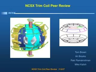
NCSX. Operation of the C1 Modular Coil in the Coil Test Facility Peer Review. June1, 2006. The objectives of this review are to consider: Installation of the C1 in the CTF Instrumentation and Data Acquisition Test Plan. C1 Operation Review Objective. Close Quarters.

E N D
NCSX Operation of the C1 Modular Coil in the Coil Test Facility Peer Review June1, 2006
The objectives of this review are to consider: Installation of the C1 in the CTF Instrumentation and Data Acquisition Test Plan C1 Operation Review Objective
Close Quarters The New Cryostat Mostly Fills The Test Enclosure
Magnetic field exposure for personnel is slightly higher for the C1 test. The barrier distance increases from 15 feet to 23 feet. The C1 cryostat is large enough to impede access to and egress from the test enclosure. Three access doors allow entrance to the enclosure with necessary procedure changes (RLM: von Halle). May become classified as a Confined Space ES&H Changes
304 stainless steel legs (SE144-030)for strength One leg fixed in X&Y, three on roller supports EM loads on baseplate for boil-off reservoir require tie-downs C1 Installation
Coil Flow Diagram The C1 Coil Has Been Plumbed As 9 Separate Single-Phase Flow Paths and One Two-Phase Supply For The Lead Block Bleeds
Teflon tubing with Swagelok joints and custom backing inserts were not reliable 40 psig was the best pressure achieved The previous style of insulating G-10 pipe nipples will be used in the plumbing The Plumbing B-Plan
Bus Conductor 500 MCM Welding Cable Insulated with Teflon FEP Shrink Tubing Has Successfully Been Tested to 58 kV
Bus Bracing A Robust Support Has Been Fabricated To Both Partially Relieve The Leads From Load And To React Bus-Bus Forces Clamping force of 11300 N/m or 65 lbf/in is required on close conductors D. Williamson has asserted that the coil leads are not particularly fragile
Maximum voltage across coil is expected to be approximately 499 volts The G11CR lead sleeves designed and machined for the production coils are being used for this test set-up Lead Insulation
Main purpose – calibrate FE models with actual data Improves confidence with which models can be used for future what-if inquiries. Secondary purpose – assess cooldown/recovery performance from ambient temperature and after pulses Test Objectives
3 measurement approaches Extensive strain gauge array Mechanical displacement measurement Manual measurement of total width of both winding packs before and after Dimensional/Deflection Measurements
Strain Gauge Locations • 15 of K. Freudenberg’s 20 requested locations are instrumented
Mechanical Measurement • Box Dimensions are 94” X 116.5” ID with wall thickness of 6” • Three tubes needed • 9.5 foot outer tube ss tube, .875 OD, .675” ID. (purchased) • 8 inch ss tube (box entrance) .75” OD, .6875” ID • 10 foot inner ss tube ¼ diameter • Three angles needed (2” X 3”) (.1875 thick). These may be from local boat supply store. (Tentatively purchased two anchors.)
Extensive strain gauge and t/c data collection system V/I resistance inference This is a key feature as it is prototypical of the first-plasma machine protection scheme ADMINISTRATIVE control of coil temperature through resistance value (wait for next pulse until cool) Thermal Measurements
Fiberglass convection insulation will be installed on coil with fiberglass rope Only outer aspect of coil will be exposed to cooling Two T/C’s will be installed near the winding packs on coolant tubes. The resulting temperatures will be used to monitor the deltaT between the windings and the MCWF. A 50C difference has been recommended. Temperature Differentials
Lift the both ends of the cable bus assembly and megger pole-pole to 3 kV Restore the bus at the coil end and megger the warm coil to ground to 7.5 kV Completely restore the bus and measure the warm circuit resistance from the rectifier room Collect winding pack width data prior to cool-down Cool the coil to ~80K with proper data collection Test Sequence
Measure the cold circuit resistance from the rectifier room Perform basic shot sequence with T/C, strain archival and V/I cooldown checks Warm up to install mechanical measurement rig 5 kA room temperature pulse for K.F. Cool down, repeat shot sequence, collect previous data plus displacements Warm up facility Measure final winding pack dimensions Test Sequence (cont.)
Current Waveforms for Test The 2T Scenario from the Rev. 4 GRD offers 36.5 kA with an I**2t of 1.15e9 a**2sec.
Protective Settings Maximum “On” time – 2.3 seconds - no change from TRC Tau (thermal) – 200 seconds – no change Minimum cycle time – 900 seconds – no change I**2t max – 1.6e9 a**2sec – no change Imax – 38.5 kA up from 33 kA Protective Circuitry