Download
1 / 10
100 likes | 243 Views
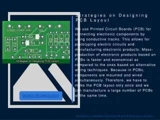
Printed Circuit Board Layout Narrative plus Preliminary PCB Layout. Preliminary pcb LAYOUT. Seraj Dosenbach Greg Lammers Beau Morrison Ananya Panja. PCB LAYOUT. 3.45 inches. 3.7 inches. MAIN PCB COMPONENTS. TOP LAYER 2 H- Bridges Microcontroller Level Translator Headers.

E N D
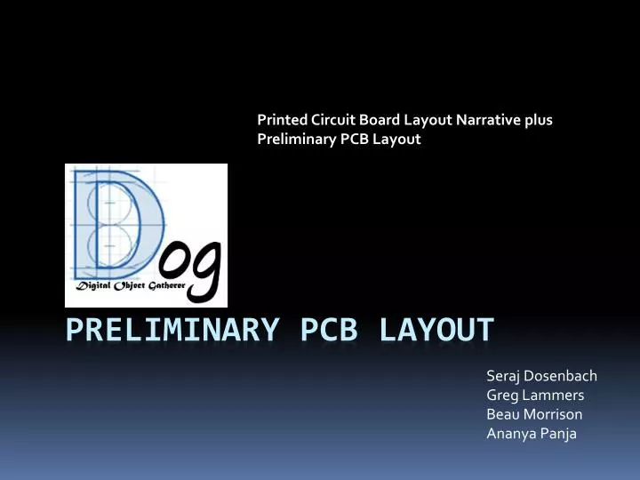
Printed Circuit Board Layout Narrative plus Preliminary PCB Layout Preliminary pcb LAYOUT SerajDosenbach Greg Lammers Beau Morrison AnanyaPanja
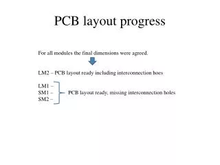
PCB LAYOUT 3.45 inches 3.7 inches
MAIN PCB COMPONENTS TOP LAYER • 2 H- Bridges • Microcontroller • Level Translator • Headers BOTTOM LAYER • Power supply
LAYOUT CONSIDERADTIONS-POWER SUPPLY • Using decoupling capacitors between the GND &VDD terminals of IC (Voltage Regulators) • Using bulk capacitors between the power terminals to decouple high frequency noise • Using PI filter (14.4 v-5v VRegulator) and LC filter(14.4-12 v VRegulator) • Have a single point power system- 1 main ground and power trace • Shorter and wider traces for power supply • Gnd and Power traces running parallel • Gnd trace very wide( >200 mils) because of high current
LAYOUT CONSIDERADTIONS-μC • Placing the crystal close to the MCU • Oscillator and reset line should not run parallel to the high current traces • Reference voltage of ADC lines should be connected to the direct power supply and not to digital Vcc & Gnd
LAYOUT CONSIDERADTIONS-OTHERS • Components placed according to the package design Hbridge Hbridge High switching current circuit Micro- Controller Analog Digital circuit • Using 45 degree angle trace turns instead of 90 degrees to prevent acid trapping