Download
1 / 13
130 likes | 251 Views
Linac 4 Diagnostics. L4: K. Hanke, M.Pasini (requirements, specifications, integration) AB/BI: U.Raich et al. (technical responsibility). General Remarks. We divide the diagnostics in two main categories: commissioning and day-to-day operation.

E N D
Linac 4 Diagnostics L4: K. Hanke, M.Pasini (requirements, specifications, integration) AB/BI: U.Raich et al. (technical responsibility)
General Remarks We divide the diagnostics in two main categories: commissioning and day-to-day operation. The first will be used to find the right settings of the machine and to study the beam quality and machine performance. The second will be used to survey the machine and for fine tuning.
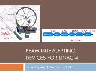
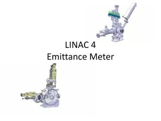
Commissioning source/LEBT: intensity: retractable Faraday cup and beam current transformer. emittance: scanning slit device with SEM grid (also steering, quantify sc compensation and commission pre-chopper; time resolution required) measurement in stages: source, first solenoid, RFQ input plane energy spread: temporary set-up with slit, spectrometer and SEM grid; read-out of SEM time resolved; additional FC at exit of spectrometer line. RFQ and chopper line: IPHI diagnostic line (TOF energy measurement, dipole, wire scanners, pick-ups). chopper line: two beam current transformers and BSHM
Commissioning DTL tank 1, 2, 3: movable diagnostics bench (MB): transmission, transverse and longitudinal emittance, energy and energy spread, set rf phase and voltage. moving slit device (transv. emittance) energy degrader (set phase) Faraday cup time-of-flight energy measurement bunch length measurement (Feschenko monitor) CCDTL, SCL: setting-up using the permanently installed diagnostics full commissioning (only at high energy): transport the beam to a permanently installed measurement line at the exit of the linac (depending on installation schedule) energy: spectrometer dipole in the ML and time-of-flight (phase pu) in the linac bunch length measurement (Feschenko monitor)
Operation source/LEBT/RFQ/chopper line: intensity: retractable Faraday cup and beam current transformer. profile: SEM grid. RFQ and chopper line: intensity: two beam current transformers permanently installed upstream and downstream of the chopper. position/phase/intensity: 3 pick-ups
Operation DTL, CCDTL, SCL: position/phase/intensity: after each tank of the DTL, after each of the 8 modules of the CCDTL and after each of the 4 modules of the SCL. combined position and phase pu, which measures also the beam current within 5%. beam loss (interlock!): BLMs along the linac and transfer line. beam current: in addition “real” beam current transformers after DTL, CCDTL, SCL and in the transfer line (HEBT). beam profile (SEM grids): after tank 3 of the DTL, after modules 4 and 8 of the CCDTL and after modules 2 and 4 of the SCL.
Exit of Linac and Transfer Line exit of linac: measurement line for transverse and longitudinal emittance and energy, transformer transfer line: position/phase/intensity: pick-ups, transformers and beam loss monitors.
Diagnostics Overview DTL SEM Grid Beam Current Transformer Beam Loss Monitor Position, Intensity and Phase pick-up BLM BLM BLM DTL tank1 DTL tank2 DTL tank3
Diagnostics Overview CCDTL 1-4 CCDTL module2 CCDTL module1 BLM BLM CCDTL module3 CCDTL module4
Diagnostics Overview CCDTL 2-8 CCDTL module6 CCDTL module5 BLM BLM CCDTL module7 CCDTL module8
Diagnostics Overview SCL SCL module2 SCL module1 BLM SCL module4 SCL module3 BLM
Technical Specifications Need input from AB/BI - Beam current transformer - SEM Grid - Bunch Length Monitor - Time of Flight - Spectrometer dipole - Phase, position and current pick-up - Beam Loss Monitor