Download
1 / 14
140 likes | 156 Views
Explore GasP pipeline, a minimal control circuit for asynchronous circuits optimizing performance and power dissipation. Learn about design guidelines, simulation results, and key contributions.

E N D
97.575 Project : GasP pipeline in asynchronous circuit Wilson Kwan M.A.Sc. Candidate Ottawa-Carleton Institute for Electrical & Computer Engineering (OCIECE) Carleton University Ottawa, Canada April 17, 2002
Outline of the presentation • What is GasP pipeline? • Building blocks of GasP pipeline. • Design Guidelines of GasP pipeline. • Simulation result. • Contributions. • Milestones of the project.
What is GasP pipeline? • GasP family of asynchronous circuit is a minimal control circuit for the pipeline. • GasP pipeline is composed of "Place" and "Path" circuits. "Place" circuit is designed to hold the source data. "Path" circuit is designed to control the flow of data between "Place" circuit. • One control signal wire is used to communicate between the pipelines.
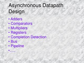
Building blocks of GasP pipeline • Two inverters connected back to back as a data latch and keeper (Place circuit) • NAND structure circuit is to collaborate the signals from previous place circuit and next place circuit (Path circuit)
0 1 1 Source data Block Diagram of GasP pipeline
Design Guidelines of GasP pipeline. (I) • - Each stage of GasP pipeline operates at the speed of a three-inverter ring oscillator. • - The forward latency is long while the reverse latency is short. • - Derive the transistor size formula, user can optimize the widths of the transistor and obtain the uniform transistor delay. • - Write the scripts to automate the job of finding the optimal transistor widths for delay time.
Design Guidelines of GasP pipeline. (II) • - To equalize the performance of each pipeline stage, all control circuits use the same number of logic gates, usually three or five, in every closed loop. • - Even numbers of gate-delays of both forward and reverse latency. • - Choose the shorter value for the uniform gate delay gives more speed at the cost of more area and more power.
Simulation result. • Initial guess of the transistor sizes: “a” inverter : 2u/0.35u “z” inverter : 1u/0.35u Self-reset circuit : 9u/0.35u , 2u/0.35u : 50ps y pass transistor : 9u/0.35u : 150ps p pass transistor : 1.5u/0.35u : 25ps For the forward latency: Estimated delay is 115 ps. Further simulation are needed.
Contributions. • GasP pipeline minimizes the structure of asynchronous pipeline control circuit. • One control signal wire is used to communicate between two stages of pipeline. • High performance and low power dissipation can be achieved by reducing the number of transistors in the control circuit.
Reference • 1) I.E. Sutherland, “Micropipeline,” Comm. ACM, vol. 32, no.6, pp. 720-738, June 1989. • 2) I.E. Sutherland and Scott Fairbanks, “GasP: A Minimal FIFO Control”, 2001. • 3) J. Ebergan, “Squaring the FIFO in GasP,” Proc. of the Seventh International Symposium on Advanced Research in Asynchronous Circuit and Systems, 2001. • 4) I.E. Sutherland, B. Sproull, and D. Harris, “Logic Effort: Designing Fast CMOS circuits. Morgan Kaufmann Publishers, Inc., 1999.