Download
1 / 9
90 likes | 241 Views
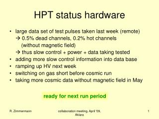
Hardware status GOLD. Generic Opto Link Demonstrator Assess the use of optical backplane connectivity for use on L1Calo. GOLD – why ?. Any future L1calo module will require large fibre plant to cope with the required (input) connectivity Connect optically via front panel (MPO connectors)

E N D
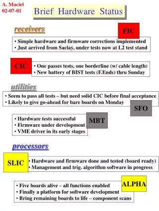
Hardware status GOLD Generic Opto Link Demonstrator Assess the use of optical backplane connectivity for use on L1Calo
GOLD – why ? Any future L1calo module will require large fibre plant to cope with the required (input) connectivity • Connect optically via front panel (MPO connectors) • Cheapest, most conventional • Least convenient wrt system maintenance • Opto-electrical conversion on rear transition modules • Considerable power dissipation outside module cage • xGb/s electrical routing required from back to front module • Opto connectors from RTM to front module, mid board transceivers • Reduce xGb/s track length • Avoid impedance discontinuities RTM/connector/front module • High density interconnect • front 2 1 • back • RTM SNAP12 3 3
Gold floor plan • Z3 • ATCA • daughter modulew. 4*FMC connector • 8 processors • SFP / SNAP12 out • Merger / control • SystemACEconfig • Opto • Z2 • Z1
Gold floor plan • Z3 • ATCA • daughter modulew. 4*FMC connector • 8 processors • SFP / SNAP12 out • Merger / control • Local routing • SystemACEconfig • Opto • Z2 • Z1
Gold floor plan • Z3 • ATCA • daughter modulew. 4*FMC connector • 8 processors • SFP / SNAP12 out • Merger / control • Local routing • SystemACEconfig • Opto • Z2 • Z1
GOLD • Data concentrator scheme : many in, few out • ATCA form factor (8U x 280 mm) • Standard Zone1 connectivity (2*-48V supply scheme) • Currently no plans for use of Zone2 electrical connectivity • Zone3 (RTMs) 6.5Gb/s optical links • 8 processors, 1 merger XC6VLX240T/550T-FFG1759 (24/36 * GTX link) • Optical inputs from backplane via bare fibre ribbons, 144 fibres • 12 * SNAP12 optical receivers (baseline: standard pin-out, not Avago) • Electrical link fan-out (*2) with CML buffers (SY58011 or similar) • ‘Realistic’ fanout scheme would require knowledge of algorithms xGb/s routing on daughter module carryingSNAP12 + fanoutchips • Allow for full size or half size modules • Set of daughters for both SNAP12 and Avago transceivers • 4 GTX outputs per processor into merger FPGA • 1*SNAP12 out from control/merger FPGA • Few SFP opto links for control purposes (incl. serialised VME) • Clock recovery, jitter cleaner and clock fanout as on BLT • Parallel connectivity (up to 1Gb/s) via differential lanes only • Run ~50 lanes from each processor into merger • Use remaining ~350 links on each processor to interlink neighbours • Configuration via SystemACE (CompactFlash)
Test daughter • Half size module • 3* SNAP12 receive • 36 * fanout (*2, CML) • 2 FMC connectors • 3 * SNAP12 transmit • SNAP12 control CPLD
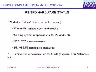
Optical backplane connectors • Available from a couple of manufacturers • Individual or 4-connector housings available • MT connectors for 12-36 fibres each, dependent on manufacturer (proprietary) • MT-to-MTP cable assemblies available from manufacturer only • expensive • MTP/MPO connectors for 12-72 fibres in single-connector housing • Takes more space than proprietary approach • 12-fibre ribbon will yield insufficient connection density on ATCA RTM boards • 24-fibre ribbons starting to become popular • Have a local supplier for custom made MTP 24-fibre ribbons and fanout cords (from January?) • Have ordered components : individual connectors, MTP compatible • Opto/PCB purely mechanical interface only, allow for change of concept later
GOLD status / outlook • Components have been identified, including optical backplane connectors • Floor planning under way • Schematic capture started • Design along the lines of Xilinx ML605 (V6 specific) and BLT • First module to go into production is test daughter for transmission tests • SNAP12 • Data source 3 fibre ribbons • Data sink 3 fibre ribbons • Build module according to ATCA standard and with baseline backplane opto connector • Should provide input to L1Calo prototyping • Reconsider module size and optical interface upon transition from demonstrator to prototyping phase.