Download
1 / 31
310 likes | 607 Views
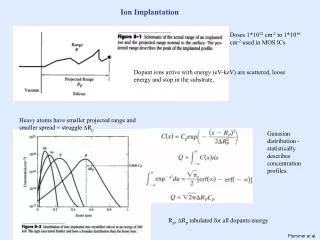
Modulator Design for Plasma Ion Implantation. Professor Michael Bradley Dale Heggie, Joel Leslie, Curtis Olson March 24 th , 2004. Objective. Convert an existing vacuum chamber into a plasma ion source for Ion Implantation. Applications in Materials Processing. Electronics Industry

E N D
Modulator Design for Plasma Ion Implantation Professor Michael Bradley Dale Heggie, Joel Leslie, Curtis Olson March 24th, 2004
Objective Convert an existing vacuum chamber into a plasma ion source for Ion Implantation
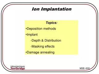
Applications in Materials Processing • Electronics Industry • Semiconductor doping • IC Fabrication • Mechanical Treatment • Surface hardness • Frictional Properties • Biomedical Implants • Biocompatible materials
Applications in Materials Processing • Electronics Industry • Semiconductor doping • IC Fabrication • Mechanical Treatment • Surface hardness • Frictional Properties • Biomedical Implants • Biocompatible materials
What’s a plasma?? Four States of Matter • Solid • Liquid • Gas • Plasma
Plasma Examples • Neon lights • Lightning • Sun • Aurora Borealis
Plasma Examples • Neon lights • Lightning • Aurora Borealis
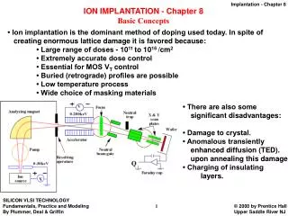
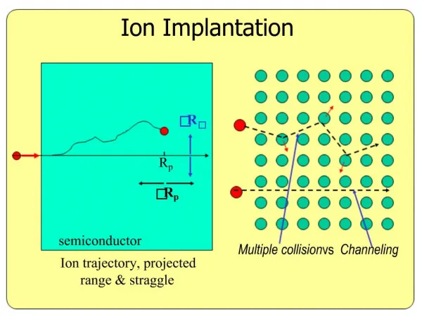
Silicon PII Material Processing • Insert sample into chamber • Strike a plasma • Apply high negative voltage • Ions hit the sample and are implanted + + + + + + + -5 kV
PII Material Processing • Characterize the effects of implant depth and dose + + + + Sample Material Sample Holder -5 kV -10 kV -20 kV
Implant Implications • Kinetic energy is transferred into heat • Sample overheating from continuous implant • Requires pulsed voltage + + + + + + +
Voltage Pulsing + + + + + + + + + • Energy contamination from rising and falling edges Voltage Implanting Cooling Time
+ - Final System Vacuum Chamber Modulator High Voltage Source
Time Start Modulator Design To Vacuum • Solid state transistor modules • One master timer • Expandable Master Timer Optical Fiber High Voltage Source + -
Circuit Performance • 5 switching modules • Excellent rise and fall times • Expandable without affecting performance Timer High Voltage
Successful Implant • 5 switching modules • 1600 V negative bias • 2” Silicon Wafer • Short Nitrogen implant
Special Thanks • Dr. Michael Bradley • Dave McColl, P. Eng. • Dr. Ajay Singh • Dr. Akira Hirose • Perry Balon • Vic Meyer, Electrical Shops
Master Controller • Circuit Description • Monostable 555 for implant duration • Astable 555 for pulse frequency • Features • Duty cycle variation • Implant Time (5, 10, 30 seconds) • Start Control
Circuit Development • High Voltage Switching Units • PC Board layout in Traxmaker • Fabricated by Electrical Engineering Shops
Vacuum Chamber Results • 2 x 10⁻⁷ Torr base pressure • 0.01% impurities from background gas
Sample Holder • Secure silicon wafer inside chamber • Thermal conductivity • Aluminum
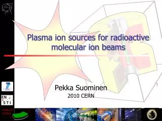
Plasma Generation • Raise to 2 mTorr pressure with Nitrogen • Filament generation
By the Numbers… Vacuum Chamber • Goal - Base pressure < 1 µTorr • Result – 2 x 10⁻⁷ Torr High Voltage Switching • Goal - < 10 microsecond rise and fall • Result – 300 ns rise, 700 ns fall
Switching Problems • Less than 1% energy contamination
Overall Circuit Performance • 5 modules at 1600 Volts • Expandable without affecting performance
Vacuum Chamber • Base pressure • 1 in 10 000 contamination
Langmuir Probe • Characterize our plasma for accurate implant doses • Ion saturation current of 12 mA • Ion Density of Plasma (~2 x 10⁹ ions/cm3) • 0.57% ionization
Modulator Design • Modules • Insulated gate bipolar junction transistor (IGBT) • Internal battery power • Optical Isolation • Synchronization
Future Design Projects • High Voltage Isolation • Metal boxes • Fast Zener clamping for each module • Increase Plasma density • Shorter implant times • Increase saturation current via RF source • Better Power Supply