Download
1 / 1
10 likes | 171 Views
Nucl. Sci. Symposium Oct. 25 – 30, 2009 Orlando, USA N13 - 246. Design and Construction of a First Prototype Muon Tomography System with GEM Detectors for the Detection of Nuclear Contraband M. Hohlmann 1 , K. Gnanvo 1 , L. Grasso 1 , J. B. Locke 1 , A. Quintero 1 , D. Mitra 2

E N D
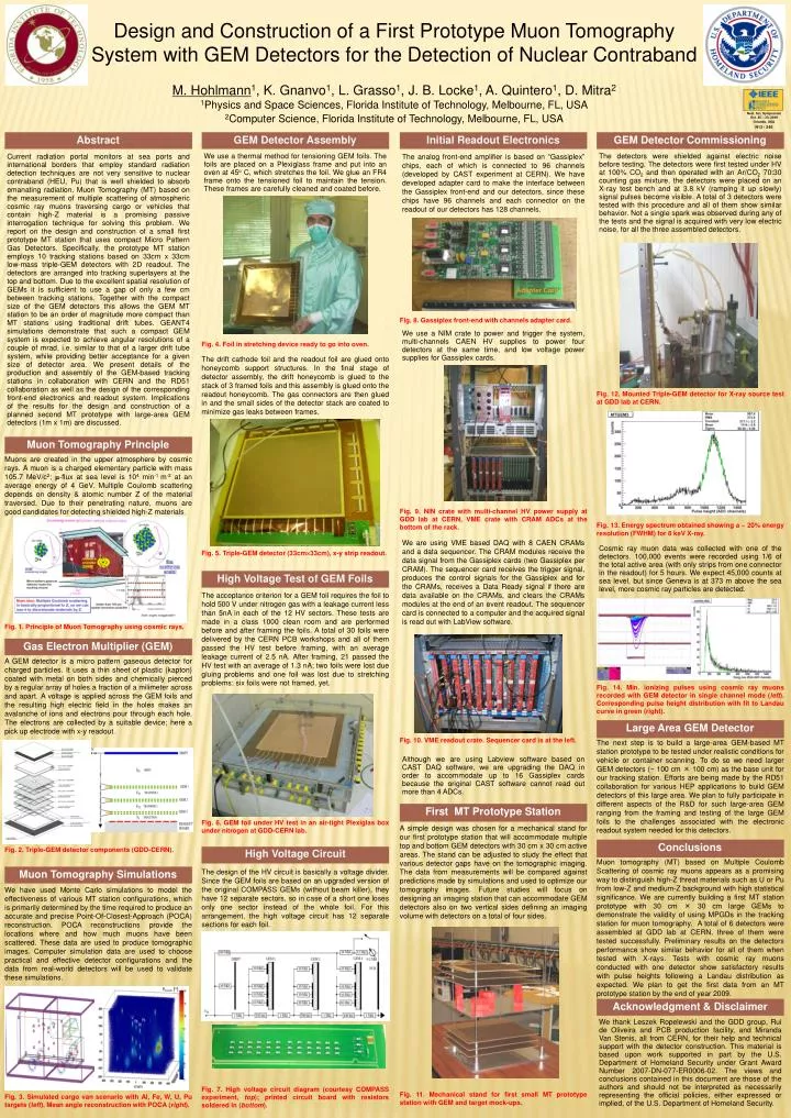
Nucl. Sci. Symposium Oct. 25 – 30, 2009 Orlando, USA N13 - 246 Design and Construction of a First Prototype Muon Tomography System with GEM Detectors for the Detection of Nuclear Contraband M. Hohlmann1, K. Gnanvo1, L. Grasso1, J. B. Locke1, A. Quintero1, D. Mitra2 1Physics and Space Sciences, Florida Institute of Technology, Melbourne, FL, USA2Computer Science, Florida Institute of Technology, Melbourne, FL, USA Abstract GEM Detector Assembly Initial Readout Electronics GEM Detector Commissioning We use a thermal method for tensioning GEM foils. The foils are placed on a Plexiglass frame and put into an oven at 45o C, which stretches the foil. We glue an FR4 frame onto the tensioned foil to maintain the tension. These frames are carefully cleaned and coated before. The analog front-end amplifier is based on “Gassiplex” chips, each of which is connected to 96 channels (developed by CAST experiment at CERN). We have developed adapter card to make the interface between the Gassiplex front-end and our detectors, since these chips have 96 channels and each connector on the readout of our detectors has 128 channels. The detectors were shielded against electric noise before testing. The detectors were first tested under HV at 100% CO2 and then operated with an Ar/CO2 70:30 counting gas mixture, the detectors were placed on an X-ray test bench and at 3.8 kV (ramping it up slowly) signal pulses become visible. A total of 3 detectors were tested with this procedure and all of them show similar behavior. Not a single spark was observed during any of the tests and the signal is acquired with very low electric noise, for all the three assembled detectors. Current radiation portal monitors at sea ports and international borders that employ standard radiation detection techniques are not very sensitive to nuclear contraband (HEU, Pu) that is well shielded to absorb emanating radiation. Muon Tomography (MT) based on the measurement of multiple scattering of atmospheric cosmic ray muons traversing cargo or vehicles that contain high-Z material is a promising passive interrogation technique for solving this problem. We report on the design and construction of a small first prototype MT station that uses compact Micro Pattern Gas Detectors. Specifically, the prototype MT station employs 10 tracking stations based on 33cm x 33cm low-mass triple-GEM detectors with 2D readout. The detectors are arranged into tracking superlayers at the top and bottom. Due to the excellent spatial resolution of GEMs it is sufficient to use a gap of only a few cm between tracking stations. Together with the compact size of the GEM detectors this allows the GEM MT station to be an order of magnitude more compact than MT stations using traditional drift tubes. GEANT4 simulations demonstrate that such a compact GEM system is expected to achieve angular resolutions of a couple of mrad, i.e. similar to that of a larger drift tube system, while providing better acceptance for a given size of detector area. We present details of the production and assembly of the GEM-based tracking stations in collaboration with CERN and the RD51 collaboration as well as the design of the corresponding front-end electronics and readout system. Implications of the results for the design and construction of a planned second MT prototype with large-area GEM detectors (1m x 1m) are discussed. Adapter Card Fig. 8. Gassiplex front-end with channels adapter card. We use a NIM crate to power and trigger the system, multi-channels CAEN HV supplies to power four detectors at the same time, and low voltage power supplies for Gassiplex cards. Fig. 4. Foil in stretching device ready to go into oven. The drift cathode foil and the readout foil are glued onto honeycomb support structures. In the final stage of detector assembly, the drift honeycomb is glued to the stack of 3 framed foils and this assembly is glued onto the readout honeycomb. The gas connectors are then glued in and the small sides of the detector stack are coated to minimize gas leaks between frames. Fig. 12. Mounted Triple-GEM detector for X-ray source test at GDD lab at CERN. Muon Tomography Principle Muons are created in the upper atmosphere by cosmic rays. A muon is a charged elementary particle with mass 105.7 MeV/c2; -flux at sea level is 104 min-1 m-2 at an average energy of 4 GeV. Multiple Coulomb scattering depends on density & atomic number Z of the material traversed. Due to their penetrating nature, muons are good candidates for detecting shielded high-Z materials. Fig. 9. NIN crate with multi-channel HV power supply at GDD lab at CERN, VME crate with CRAM ADCs at the bottom of the rack. Fig. 13. Energy spectrum obtained showing a ~ 20% energy resolution (FWHM) for 8 keV X-ray. We are using VME based DAQ with 8 CAEN CRAMs and a data sequencer. The CRAM modules receive the data signal from the Gassiplex cards (two Gassiplex per CRAM). The sequencer card receives the trigger signal, produces the control signals for the Gassiplex and for the CRAMs, receives a Data Ready signal if there are data available on the CRAMs, and clears the CRAMs modules at the end of an event readout. The sequencer card is connected to a computer and the acquired signal is read out with LabView software. Cosmic ray muon data was collected with one of the detectors. 100,000 events were recorded using 1/6 of the total active area (with only strips from one connector in the readout) for 5 hours. We expect 45,000 counts at sea level, but since Geneva is at 373 m above the sea level, more cosmic ray particles are detected. Fig. 5. Triple-GEM detector (33cm33cm), x-y strip readout. High Voltage Test of GEM Foils The acceptance criterion for a GEM foil requires the foil to hold 500 V under nitrogen gas with a leakage current less than 5nA in each of the 12 HV sectors. These tests are made in a class 1000 clean room and are performed before and after framing the foils. A total of 30 foils were delivered by the CERN PCB workshops and all of them passed the HV test before framing, with an average leakage current of 2.5 nA. After framing, 21 passed the HV test with an average of 1.3 nA; two foils were lost due gluing problems and one foil was lost due to stretching problems; six foils were not framed, yet. Fig. 1. Principle of Muon Tomography using cosmic rays. Gas Electron Multiplier (GEM) A GEM detector is a micro pattern gaseous detector for charged particles. It uses a thin sheet of plastic (kapton) coated with metal on both sides and chemically pierced by a regular array of holes a fraction of a milimeter across and apart. A voltage is applied across the GEM foils and the resulting high electric field in the holes makes an avalanche of ions and electrons pour through each hole. The electrons are collected by a suitable device; here a pick up electrode with x-y readout. Fig. 14. Min. ionizing pulses using cosmic ray muons recorded with GEM detector in single channel mode (left). Corresponding pulse height distribution with fit to Landau curve in green (right). Large Area GEM Detector Fig. 10. VME readout crate. Sequencer card is at the left. The next step is to build a large-area GEM-based MT station prototype to be tested under realistic conditions for vehicle or container scanning. To do so we need larger GEM detectors (~ 100 cm × 100 cm) as the base unit for our tracking station. Efforts are being made by the RD51 collaboration for various HEP applications to build GEM detectors of this large area. We plan to fully participate in different aspects of the R&D for such large-area GEM ranging from the framing and testing of the large GEM foils to the challenges associated with the electronic readout system needed for this detectors. Although we are using Labview software based on CAST DAQ software, we are upgrading the DAQ in order to accommodate up to 16 Gassiplex cards because the original CAST software cannot read out more than 4 ADCs. First MT Prototype Station Fig. 6. GEM foil under HV test in an air-tight Plexiglas box under nitrogen at GDD-CERN lab. A simple design was chosen for a mechanical stand for our first prototype station that will accommodate multiple top and bottom GEM detectors with 30 cm x 30 cm active areas. The stand can be adjusted to study the effect that various detector gaps have on the tomographic imaging. The data from measurements will be compared against predictions made by simulations and used to optimize our tomography images. Future studies will focus on designing an imaging station that can accommodate GEM detectors also on two vertical sides defining an imaging volume with detectors on a total of four sides. Conclusions Fig. 2. Triple-GEM detector components (GDD-CERN). High Voltage Circuit Muon tomography (MT) based on Multiple Coulomb Scattering of cosmic ray muons appears as a promising way to distinguish high-Z threat materials such as U or Pu from low-Z and medium-Z background with high statistical significance. We are currently building a first MT station prototype with 30 cm × 30 cm large GEMs to demonstrate the validity of using MPGDs in the tracking station for muon tomography. A total of 6 detectors were assembled at GDD lab at CERN, three of them were tested successfully. Preliminary results on the detectors performance show similar behavior for all of them when tested with X-rays. Tests with cosmic ray muons conducted with one detector show satisfactory results with pulse heights following a Landau distribution as expected. We plan to get the first data from an MT prototype station by the end of year 2009. Muon Tomography Simulations The design of the HV circuit is basically a voltage divider. Since the GEM foils are based on an upgraded version of the original COMPASS GEMs (without beam killer), they have 12 separate sectors, so in case of a short one loses only one sector instead of the whole foil. For this arrangement, the high voltage circuit has 12 separate sections for each foil. We have used Monte Carlo simulations to model the effectiveness of various MT station configurations, which is primarily determined by the time required to produce an accurate and precise Point-Of-Closest-Approach (POCA) reconstruction. POCA reconstructions provide the locations where and how much muons have been scattered. These data are used to produce tomographic images. Computer simulation data are used to choose practical and effective detector configurations and the data from real-world detectors will be used to validate these simulations. scatt [o] Acknowledgment & Disclaimer We thank Leszek Ropelewski and the GDD group, Rui de Oliveira and PCB production facility, and Miranda Van Stenis, all from CERN, for their help and technical support with the detector construction. This material is based upon work supported in part by the U.S. Department of Homeland Security under Grant Award Number 2007-DN-077-ER0006-02. The views and conclusions contained in this document are those of the authors and should not be interpreted as necessarily representing the official policies, either expressed or implied, of the U.S. Department of Homeland Security. mm Fig. 7. High voltage circuit diagram (courtesy COMPASS experiment, top); printed circuit board with resistors soldered in (bottom). Fig. 11. Mechanical stand for first small MT prototype station with GEM and target mock-ups. Fig. 3. Simulated cargo van scenario with Al, Fe, W, U, Pu targets (left). Mean angle reconstruction with POCA (right).