Download
1 / 20
200 likes | 223 Views
EuCARD-WP7-HFM MPWG Bending Test. Pierre MANIL CEA/iRFU/SIS March 18, 2010 at Wroclaw. Ackowledgement. Thanks to the task and working group members. Especially: @ CERN : Attilio Milanese, Juan Carlos Perez, Gijs de Rijk, Ezio Todesco @ Saclay:

E N D
EuCARD-WP7-HFMMPWGBending Test Pierre MANIL CEA/iRFU/SIS March 18, 2010 at Wroclaw
Ackowledgement • Thanks to the task and working group members. Especially: • @ CERN: Attilio Milanese, Juan Carlos Perez, Gijs de Rijk, Ezio Todesco • @ Saclay: Mélanie Bruchon, Maria Durante, François Kircher, Jean-Michel Rifflet, Etienne Rochepault, Françoise Rondeaux • Tooling specification: MPWG • Theoretical analysis: Attilio Milanese (CERN) • Draftsman: Jean-François Millot (CEA) • Fabrication: CERN workshop, followed by Juan Carlos Perez (CERN)
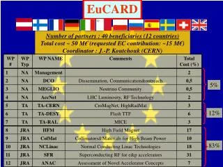
MPWG Activities EuCARD WP7: HFM Gijs de Rijk (CERN) other tasks 7.2: Support Studies Jaroslaw Polinski (WUT) 7.3: High Field Model Jean-Michel Rifflet (CEA) 7.4: HTc insert Pascal Tixador (Grenoble) Specification WG Ezio Todesco (CERN) MagnetPre-design WG myself (CEA) Cable Design WG Luc Oberli (CERN) • Preliminary models • Preliminary tests • Configuration choice • Optimization • Model realization • Realization 13 T magnet, so-called ‘Fresca 2’ HTc insert
MPWG Activities Magnet Pre-design WorkinGroup • Collaborative work between CERN and CEA • cf. talk from Jean-Michel at the beginning of the session • First task is to discriminate between two options: “ Blockvs.Cos(θ)” • cf. talk from Attilio, just before • Magnetic comparison => first analysis done • Mechanical comparison => on-going (CAST3M, ANSYS) • Feasibility • Winding => 1st step = Bending Test, next week (this talk) • Pre-stress • … • Configuration choice by April 2010 (DWG) • Magnetic Optimization » Mechanical optimization » Trials • In parallel: characterization tests
Bending Test: Goal • We know by experiencethat if the Cos(θ) design is selected, we can manage with the ends • What about the Block design ends? Flaredends like for HD2 [1] Flat racetracks Φ100 mm Block 4 Block 3 Block 2 Block 1 Pre-stress The Bending Test considersonly the Block configuration! sketch: A. Milanese picture from HD2, courtesy of LBNL
Bending Test: Historical approach • In the 80’s, the HERA magnet experienced a Block design at Saclay [2] Sol. A Stacking similar to a Block Stacking similar to a Cos(Θ) Sol. B courtesy of J.M. Rifflet
Bending Test: Zones • The baseline coil geometry divides into 3 or 4 zones: • straight section (SS) parallel to the mid-plane of the magnet • hard-way bend zone (HW) in a plane containing the cable • optional straight section (OS) part on an inclined plane • easy-way bend zone (EW) on an inclined plane
Bending Test: Mockup • Cardboard mockup illustrating the zones: BLOCK 2 Straight section Hard-waybend zone (planar) Minimal radius (> 10.tcable) ~220 mm End (flat) Φ120 mm clear bore (including mechanics) Block 2 Block 1 courtesy of Attilio Milanese
Bending Test: Ideas dor the ends • “Side”: double clothoid + flat part • Flat “racetrack” end Flat end 2 layers of cable courtesy of Attilio Milanese
End shape: Analytical approach Curvaturek(x) • Analytic study by Attilio to identify ‘best’ end configurations [3] • Ideal beam is assumed • Good solution must: • Not betoo long • Be smooth up to second derivative • Be convex • Minimize the total strainenergy • Avoidpeaks of strainenergy • 5 geometries are compared: φ120 circle ellipse superellipse least energy clothoid courtesy of Attilio Milanese
End shape: Selected options • 3 geometries are selected for the Bending Test: • The best one will be kept for the FRESCA2 magnet circle ellipse superellipse
Bending Test Parameters (1/3) • Remarks: • HFM dummycableisused (seesample) • The first dummycable has a p of ~120 mm (Luc Oberli, 02/10) • (mechanicalinstabilitieswithp > 140 mm) • No insulation for the first test campaign (bare dummy cable)
Bending Test Parameters (2/3) • Remarks: • wpincludesΦb + 20 mm for mechanics • Block 2 isconsidered (minimal radius) • Nt corresponds to ~1/4 Block • Y2 corresponds to the lowest possible • position for the Block 2 Y2 sketch: A. Milanese
Bending Test Parameters (3/3) The BendingToolingwillallow to trymanydifferent configurations, withseveraldegrees of freedom for each zone
Tooling • Specified by the MPWG from Jaunary on • Detailed design by Saclay (February) • Fabricated last week at CERN • Delivered at Saclay today (18/3)! with J.F. Millot
Tooling d.o.f end (3 options) LHW = 160 LSS = 320 rW = 120 LOS = 0 / 20 / 50 80 0/5/10/15/20/25° Return end Φ121.82 Θ rb = 50 Y2 = 21.8 The full configuration corresponds to approx. 2 m / turns values in mm. with J.F. Millot
Example: flat configuration The flat configuration corresponds to approx. 1.5 m / turns with J.F. Millot
Experimental Design • Additionalparameters: • winding tension (~50 kNwithgradualdecrease) • transposition pitch
Next Steps • Bending Test: next week at Saclay • MPWG Meeting 06: Friday next week (26/3) at Saclay => Test conclusions • Configuration choice: by April • Mechanical modeling • Magnetic optimization • Mechanical characterization of the conductor: • Young modulus at RT & 2K • Thermal coefficient • Ultimate compressive stress (critical current)
References [1] Recent test results of the High Field Nb3Sn dipole magnet HD2 P. Ferracin, B. Bingham, S. Caspi, D. W. Cheng, D. R. Dietderich, H. Felice, A. R. Hafalia, C. R. Hannaford, J. Joseph, A. F. Lietzke, J. Lizarazo, G. Sabbi, X. Wang Submitted to MT21, Hefei, Oct. 2009 [2] The HERA dipole magnet: J. Pérot, J.-M. Rifflet Ref [3] Shapes of coil ends in racetrack layout for superconducting magnets A. Milanese CERN TE-Note-2010-04, Jan. 2010, EDMS 1057916 [4] FRESCA2 magnet specification SWG version 2.0, Feb. 2010, accessible on the Task 7.3 workspace + Previous talks this day