Download
1 / 13
130 likes | 216 Views
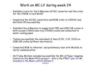
LV and HV for M1 R1 Muon. Low Voltage requirements final layout High Voltage requirements prototype cabling. VME DAQ. GEM Chamber. Tracking system. LNF Cosmic test setup. In this setup we are testing : HV passive divider HV cabling (50 m cable) LV cabling LV distributor

E N D
LV and HV for M1 R1 Muon • Low Voltage • requirements • final layout • High Voltage • requirements • prototype • cabling
VME DAQ GEM Chamber Tracking system LNF Cosmic test setup • In this setup we are testing : • HV passive divider • HV cabling (50 m cable) • LV cabling • LV distributor • LV regulator • with “final” readout with VME scalers and tdcs
Low Voltage System Tests has been performed with linear Power Supply : in LHCb we have to go to rad tol regulator(STM-CERN design) same as for LHCb wire-chambers FEE Boards are fed with LV distributor board (not in series !) Power consumption/board = 0.5A Supply voltage =2.5V 24 FEE boards /chamber 3 FEE boards / regulator 8 regulators /chamber First prototype of LV distributor done and under test on LNF cosmic setup
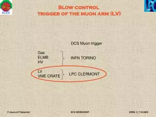
lv distribution board Low Voltage layout regulator and sensing 5 m 30 m Linear Power Supply
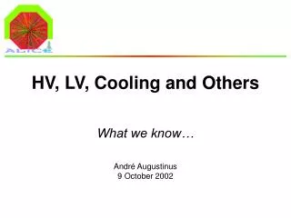
Faraday Cage brass (400 mm) FC alignment done with special tool respect to reference holes flat cables from LV distributor Faraday cage prototype done and production started
HV requirements So far: 7 HV channels/gap: the easiest and the most expensive but very dangerous in case of a trip at least the GEMs should be together • Requirements: • stay in plateau with 10 μA in the detector in LHCb • limit power consumption • protect GEMs in case of sparks • monitor current in the detector • a candidate solution with 3dividers and 3 commercial power supplies (CAEN) • HV divider (simulated by Cagliari; realized by LNF): • first prototype: high dissipation on a resistor of the G2 divider stage, leading to a change in the resistor value second prototype: test done and ok • ready for production
HV cabling inside the chamber Studies on HV connectors (commercial one have Teflon)
HV Gem divider 50 KW 50 KW current monitor 6kV/200mA -3880 -2830 -2390 -2040 -1610 -910 -500 2.2 nF 1MW 5 KW 5 KW 4kV/2mA 10 nF g1 220 KW 6 Inputs 14 Outputs 175 KW g2 210 KW 810 KW 5 KW 5 KW 1.3kV/10mA Divider made of Al2O3 with dissipating bottom layer and trimmed serigraphic resistors 10 nF g3 63 KW 75 KW
Divider Measurements working point mA Transfer fields Currents on divider
Divider Measurements working point GEM Voltages
HV System architecture “Standard” (non Rad-Tol) HV system with long HV lines (72 HV lines) • 1 SY1527 mainframe • 2 A1832N HV modules • 1 A1535N HV module • 2 A1738N HV modules • SHV-to-multiconductor patch panels SHV-to-multiwire HV PP SY 1527 System Mainframe 72 SHV 2-5 m
HV cable Long distance cable • 18 conductors shielded cable from tecnikabel • 4.5 kV nominal voltage • 1.685 euro/m (for a minimum of 2000 m) • Number of cable doubled for future upgrade • 6(+2) cables from local patch panel to M1 cavern patch panel side A • 6(+2) cables from local patch panel to M1 cavern patch panel side C Local HV PP M1 PP side A 60 m SY 1527 System Mainframe 2-5 m 5 m 72 long distance cables M1 PP side C